ATM virtual path switching node

Inactive Publication Date: 2000-03-21
JUMIPER NETWORKS INC
View PDF5 Cites 116 Cited by
  • Summary
  • Abstract
  • Description
  • Claims
  • Application Information

AI Technical Summary

Benefits of technology

It is an object of the present invention to provide an ATM virtual path switching node capable of solving the problems of the prior art, utilizing the advantages of the conventional fault detection mean

Problems solved by technology

However, the first problem of the prior art is that when faults are detected from a number of virtual paths, the processing load for generation or transmission of link fault notification signals increases, and accordingly, the virtual paths take a long time to recover from the faults.
When fault occur, and the number of v

Method used


Image

  • ATM virtual path switching node
  • ATM virtual path switching node
  • ATM virtual path switching node

Examples


first embodiment

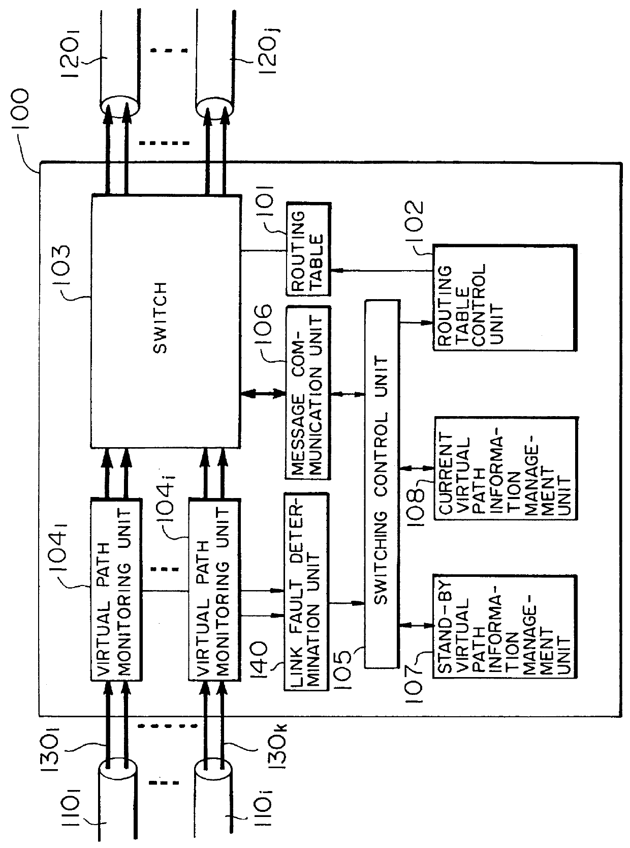
FIG. 2A shows an ATM virtual path switching node according to the present invention. Referring to FIG. 2A, reference numeral 100 denotes an ATM virtual path switching node; 110.sub.1 to 110.sub.i, input links; 120.sub.1 to 120.sub.j, output links; and 130.sub.1 to 130.sub.k, virtual paths. The ATM virtual path switching node 100 switches the virtual paths 130.sub.1 to 130.sub.k between the input links 110.sub.1 to 110.sub.i and the output links 120.sub.1 to 120j.

The ATM virtual path switching node 100 comprises a routing table 101, a routing table control unit 102, a switch 103, a virtual path monitoring units 104.sub.1 to 104.sub.i, a switching control unit 105, a message communication unit 106, a stand-by virtual path information management unit 107, a current virtual path information management unit 108, and a link fault determination unit 140. The virtual path monitoring units 104.sub.1 to 104.sub.i are arranged in correspondence with the input links 110.sub.1 to 110.sub.i, resp...

second embodiment

FIG. 3A shows an ATM virtual path switching node according to the present invention. Referring to FIG. 3A, reference numeral 300 denotes an ATM virtual path switching node; 310.sub.1 to 310.sub.i, input links; 320.sub.1 to 320.sub.j, output links; and 330.sub.1 to 330.sub.k, virtual paths. The ATM virtual path switching node 300 switches the virtual paths 330.sub.1 to 330.sub.k between the input links 310.sub.1 to 310.sub.i and the output links 320.sub.1 to 320.sub.j.

The ATM virtual path switching node 300 comprises a routing table 301, a routing table control unit 302, a switch 303, a virtual path monitoring units 304.sub.1 to 304.sub.i, a switching control unit 305, a message communication unit 306, a stand-by virtual path information management unit 307, a current virtual path information management unit 308, and a representative virtual path selection unit 340. The virtual path monitoring units 304.sub.1 to 304.sub.i are arranged in correspondence with the input links 310.sub.1 ...

third embodiment

FIG. 4 shows an ATM virtual path switching node according to the present invention. Referring to FIG. 4, reference numeral 500 denotes an ATM virtual path switching node; 510.sub.1 to 510.sub.i, input links; 520.sub.1 to 520.sub.j, output links; and 530.sub.1 to 530.sub.k, virtual paths. The ATM virtual path switching node 500 switches the virtual paths 530.sub.1 to 530.sub.k between the input links 510.sub.1 to 510.sub.i and the output links 520.sub.1 to 520.sub.j.

For the ATM virtual path switching node 500, the functions of the ATM virtual path switching nodes 100 and 300 of the first and second embodiments shown in FIGS. 2A and 3A, respectively, are combined. The ATM virtual path switching node 500 comprises a routing table 501, a routing table control unit 502, a switch 503, a virtual path monitoring units 504.sub.1 to 504.sub.i, a switching control unit 505, a message communication unit 506, a stand-by virtual path information management unit 507, a current virtual path informa...


PUM


Abstract

In an ATM virtual path switching node, upon being notified of a current virtual path by a virtual path monitoring unit, a link fault determination unit compares the number of faulty current virtual paths with a predetermined threshold value. When the number of faulty current virtual paths is equal to or larger than the threshold value, a link fault is determined, and a message communication unit transmits/receives a link fault notification signal to/from another ATM virtual path switching node. When the number of faulty current virtual paths is smaller than the threshold value, a current virtual path fault is determined, and the message communication unit transmits/receives a virtual path fault notification signal to/from another ATM virtual path switching node. The message communication unit transmits a switching control signal for designating switching from the current virtual path to a stand-by virtual path. A current virtual path information management unit manages correspondence between the current virtual path having, as one switching terminal, a self ATM virtual path switching node and a plurality of links in an ATM network.

Description

BACKGROUND OF THE INVENTION1. Field of the InventionThe present invention relates to an ATM virtual path switching node which switches a virtual path influenced by various faults generated in an asynchronous transfer mode (to be simply referred to as ATM hereinafter) network to another virtual path as a detour, thereby recovering the path from the faults.2. Description of the Prior ArtIn recent years, as the bandwidth has broadened along with the progress in the optical fiber transmission technology, a broadband ISDN (BISDN) which integrally accommodates various communication services for voice, character, and image data and provides these services to subscribers is becoming more important. An essential network technology for realizing the BISDN is the ATM technology. In ATM, any information is segmented into packets called cells each having a fixed length, and a header necessary for routing is added to each packet, thereby transmitting the information, as described in Hiroshi Shimi...

Claims


Application Information

Patent Timeline
IPC IPC(8): H04Q11/04H04L12/56H04L12/70H04Q3/00
CPCH04L49/105H04L49/555H04L49/557H04Q11/0478H04L49/254H04L2012/5619H04L2012/5627
Inventor NISHIO, MAKOTOWATANABE, HIROMITSU
Owner JUMIPER NETWORKS INC
Why Eureka
Try Eureka