Digital phase measuring system and method

a digital phase and measuring system technology, applied in the field of digital phase measuring system and method, can solve the problems of large, bulky analog circuits with a high level of complexity, large number of components, and high power consumption, and achieve the effects of improving system precision, reducing cost, and increasing processing speed

Inactive Publication Date: 2000-04-11
VISIDYNE
View PDF11 Cites 18 Cited by
  • Summary
  • Abstract
  • Description
  • Claims
  • Application Information

AI Technical Summary

Benefits of technology

It is a further object of this invention to provide such a system and method which employs fewer and simpler components resulting in lower cost and higher processing speeds.
It is a further object of this invention to provide such a system and method which requires only a single analog to digital converter which increases system precision and reduces system error.
It is a further object of this invention to provide such a system and method which uses more hardware / firmware and less software, resulting in higher processing speeds.
It is a further object of this invention to provide such a system and method which processes data at a higher rate of speed and improves system precision through averaging.
This invention results from the realization that a higher speed, simpler and more precise digital phase measuring system can be achieved by generating a quadrature clock signal from a first reference signal and using that clock signal to produce quadrature cartesian samples of a second measured signal and then converting these quadrature cartesian samples to polar coordinates in which the polar phase coordinate represents the phase difference between the two signals.
This invention results from the further realization that by selecting that the cartesian samples are taken in quadrature, the X and Y axes of the cartesian grid coincide with the polar axes of the polar grid, enabling the direct plotting of cartesian samples on a polar grid and direct determination of the phase difference, .theta., between the two signals.

Problems solved by technology

Traditionally, these devices have been large, bulky analog circuits which have a high level of complexity and incorporate a large number of components.
This is quite troublesome in a system designed to determine distance via accurate phase measurement.
Due to the number of components required to construct one of these analog systems, they tend to be quite expensive and consume i high level of power.
Further, due to its internal analog electronics, the output signal of these devices is not easily interfaced with today's digital equipment.
Additionally, due to the inaccuracy of the analog components used to construct these devices, the smallest unit of phase shift these devices are usually capable of measuring is 1.degree..
However, this only increased the number of components required to produce such a device and, additionally, increased the power consumption and cost of such devices.
Unfortunately, this modification did not greatly enhance the accuracy of the device, as the smallest unit of phase shift measurable was only reduced to 0.1.degree..
While this device is purely digital, its data processing rate is typically limited to only 100 kilohertz.
Additionally, these devices are very large and bulky, consume a high level of power, and are not easily moved from site to site.
As with the analog systems previously disclosed, this purely digital system is unable to unambiguously determine phase shift when the phase shift exceeds 359.999.degree..

Method used


Image

  • Digital phase measuring system and method
  • Digital phase measuring system and method
  • Digital phase measuring system and method

Examples


Embodiment Construction

Other objects, features and advantages will occur to those skilled in the art from the following description of a preferred embodiment and the accompanying drawings, in which:

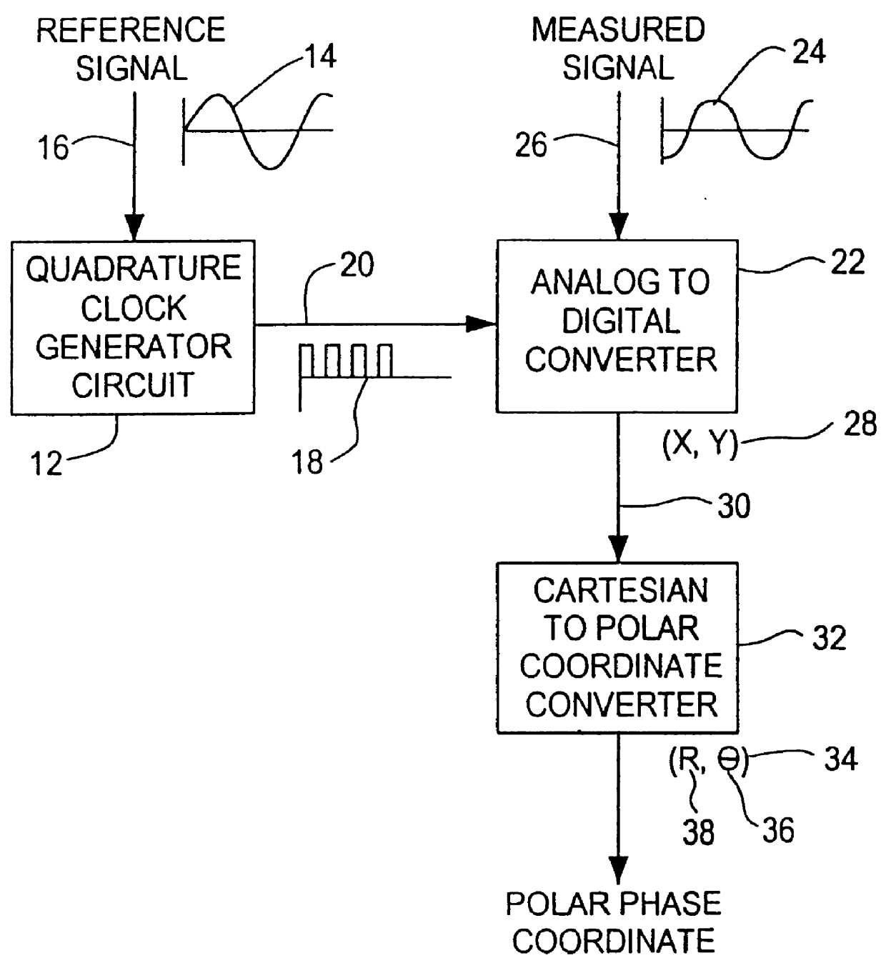
FIG. 1 is a diagrammatic view of the digital phase measuring system according to this invention;

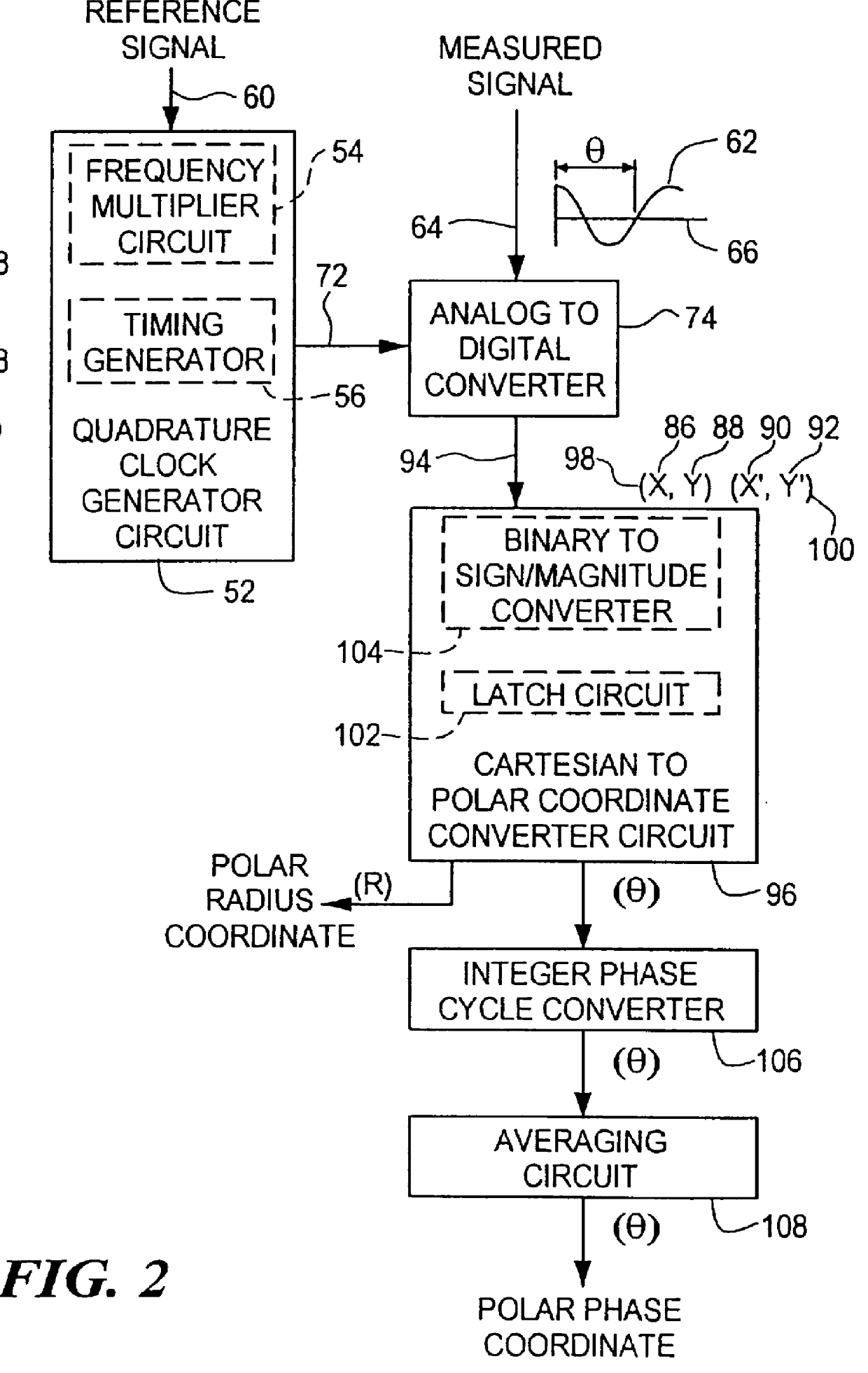
FIG. 2 is a more detailed diagrammatic view of the digital phase measuring system according to this invention including an integer phase cycle converter and an averaging circuit;

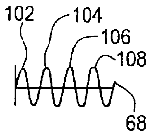
FIG. 3 is a plan view of the waveforms of the measured and reference signals as they propagate through the digital phase measuring system according to this invention; and

FIG. 4 is a flow chart of the digital phase measuring method according to this invention.

In accordance with this invention, the digital phase measuring system 10, FIG. 1, includes a quadrature clock circuit 12, responsive to a first reference signal 14 at input 16, for producing quadrature clock signals 18 on line 20. Analog to digital converter 22, responsive to quadrature c...


PUM


Abstract

A digital phase measuring system and method for measuring the phase difference between two signals including generating quadrature clock signals for a first reference signal, converting a second measured signal from analog to digital form by sampling the second measured signal using the quadrature clock signals to produce quadrature cartesian samples of the measured signal, and converting the quadrature cartesian samples to polar coordinates to define the polar phase coordinate representative of the phase difference between the two signals.

Description

This invention relates to a digital phase measuring system and method and more particularly to such a system and method in which a first signal is used to clock quadrature samples of a second signal, where these samples are converted from cartesian to polar values to directly obtain the phase of the second signal in relation to the first.BACKGROUND OF INVENTIONPhase measuring devices are used to determine the phase difference between two signals, normally a reference signal and a signal being measured. Traditionally, these devices have been large, bulky analog circuits which have a high level of complexity and incorporate a large number of components.Since the phase of the output of all analog components is a function of the amplitude of the signal applied to the component, any change in the amplitude of the signal applied to the component changes the phase of the output signal itself. This is quite troublesome in a system designed to determine distance via accurate phase measuremen...

Claims


Application Information

Patent Timeline
Patent Type & Authority Patents(United States)
IPC IPC(8): H03M1/64
CPCH03M1/64
Inventor DUCHARME, ALFRED D.BAUM, PETER N.
Owner VISIDYNE
Why Eureka
Try Eureka