However, these powered shield supports have to be of extraordinary stable design in terms of their components, in particular, their
canopy, floor skid, guide bars and various hinges, so that they are able to cope with difficult conditions of use and unfavourable loading situations.
This leads to a heavy and correspondingly expensive construction of the powered shield supports.
From the point of view of the mine operator, for reasons of application and economics, there is considerable interest in restricting the weight and hence also the costs of the shield construction.
Depending on the existing infrastructure of the mines, and also on the seam strengths which are found, it is often possible only to use powered shield supports whose weight does not exceed about 15 t to 30 t. This limitation on the weight leads to high-strength and correspondingly expensive
steel plates and steel cast parts having to be used for the highly-loaded components of the powered shield supports, which leads to considerable increases in costs in the production of the powered shield supports.
In
spite of the use of high-strength materials to
restrict the weight, overloading of individual components occurs frequently during the underground use of the powered shield supports.
Hence, high repair costs and a reduction in the service life of the powered shield supports.
In recent times, in order to reduce the investment and operating costs, powered shield supports have been used whose centre-to-centre spacing or overall width is 1.75 m instead of the previously usual dimension of 1.5 m. Further optimisation could be achieved using powered shield supports with even greater overall widths, but these would result in the abovementioned weight limitations being exceeded.
However, this solution path has not become widespread in practice, particularly because of the associated higher costs and the limitation in the force of the hydraulic guide bar due to the limitation in its cylinder
diameter.
A further
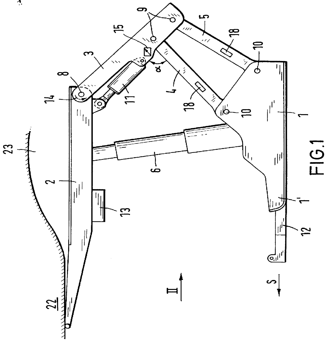
critical load situation, which can lead to overload and is referred to in mining as "tip-toeing" arises when the powered shield support, as a result of the roof load on the canopy, which projects forward against the working face, is tilted in such a way that its floor skid lifts off from the floor at the rear, i.e. the waste end, and as a consequence the powered shield support rests on the floor with only that end of the floor skid which is at the working-face side.
These
critical load situations (which are indicated only by way of example), can lead to high stresses and to damage to the components of the shield support, cannot be reliably detected in
continuous operation, particularly when the shield support at the face is equipped with an electro-hydraulic shield
control system.
It is therefore necessary to take account of the critical load situations, in that the powered shield supports must be designed very strongly in terms of construction, but which leads to increased shield weights and correspondingly high costs.

