Method and system for welding railroad rails

Inactive Publication Date: 2000-05-30
LINCOLN GLOBAL INC
View PDF17 Cites 17 Cited by
  • Summary
  • Abstract
  • Description
  • Claims
  • Application Information

AI Technical Summary

Benefits of technology

The present invention relates to a method and system for using gas shielded arc welding to join the spaced ends of railroad rails in the field, which method and system result in an economical, rapid and mechanically and metallurgically sound technique.
A further object of the invention is the provision of a method and system which employs the concept of a metal barrier plate structured so as to span the gap between the spaced rails at the bottom of the bases thereof and to underlie the bottoms outwardly adjacent the gap and to be fixed relative to the rails so as to preclude distortion or movement thereof by expansion of the rails during a preheating operation and to prevent distortion of the barrier plate by the welding arc during the welding operation.

Problems solved by technology

This need to reduce vibration has caused a substantial increase in the desire to actually butt weld the rails in high speed, high weight rail systems.
In this process, very little slag is created, which was a problem with the submerged arc and electroslag processes.
Such slag created in those processes can result in inclusions in the metal, especially at the interface between the molten metal and the ends of the rails.
These inclusions cause failures.

Method used


Image

  • Method and system for welding railroad rails
  • Method and system for welding railroad rails
  • Method and system for welding railroad rails

Examples


Embodiment Construction

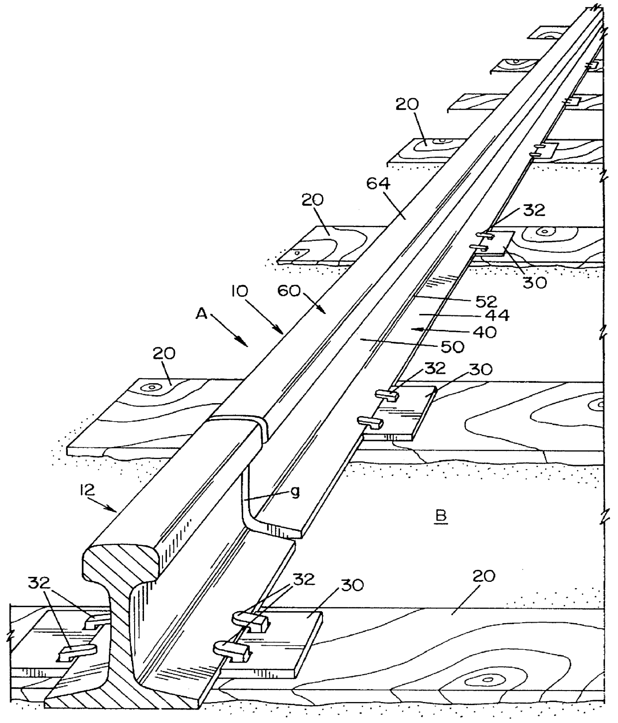
Referring now to the figures wherein the drawings are for the purpose of illustrating the preferred embodiment of the invention only and not for the purpose of limiting same, FIG. 1 shows a railroad rail A laid on right-of-way bed B and including rails 10, 12 to be joined to form a continuous welded rail (CWR) and supported on bed B by ties 20, steel support caps 30 and spikes 32. Rails 10, 12 are spaced to define a gap g which is to be filled by molten metal to join the two rails 10, 12 together as a continuous rail in the field, as opposed to a plant assembly of continuous rail. Gap g can be the gap between two sections of rail to be repaired or the gap between two sections of rail which are to be initially installed as a continuous welded rail system. If the gap g is used for repairing, it is sometimes necessary to cut the rails and insert a long rail section. This process is used for repairing rails which have fractures, joints which have fractured or joints which are defective....


PUM

PropertyMeasurementUnit
Lengthaaaaaaaaaa
Lengthaaaaaaaaaa
Thicknessaaaaaaaaaa

Abstract

A method of gas shielded arc welding steel railroad rails spaced from each other to define a longitudinal gap comprises the steps of providing an elongated steel barrier plate across the gap at the bottom of the spaced rails, and filling gap above the barrier plate with a molten steel from an advancing filler metal electrode by a gas shielded electric arc welding process. The barrier plate has a central portion received in the gap and longitudinally extending recesses laterally outwardly adjacent to the central portion and which underlie the bottoms of the rails at the bottom of the gap.

Description

The present invention relates to a method and system for welding the spaced ends of rails and more particularly welding two spaced railroad rails in the field by an arc welding process.INCORPORATION BY REFERENCEThrough the years, a tremendous amount of effort have been devoted to joining spaced railroad rails by some type of butt welding process. Such efforts have generally proven costly and unsuccessful, due to limitations of the processes used, the required time for accomplishing the welding process, the cost of performing the welding process and / or the inability to obtain successful, long-lasting joints. In Devletian U.S Pat. No. 4,429,207, the most common electric arc welding process is illustrated wherein the electroslag welding procedure is used to fill the gaps between spaced railroad rails in the field. This process involves filling the gap between the rails with a pool of molten metal covered by an appropriate slag. To prevent the mass of molten metal from flowing from the ...

Claims


Application Information

Patent Timeline
IPC IPC(8): B23K9/038B23K9/02B23K9/00B23K9/06B23K9/067B23K9/16E01B11/50E01B11/00
CPCB23K9/0026B23K9/0213B23K9/0216E01B11/50B23K9/067B23K9/162B23K9/038B23K2201/26B23K2101/26
Inventor MORLOCK, MICHAEL J.
Owner LINCOLN GLOBAL INC
Why Eureka
Try Eureka