Method and system for transmitting seismic data to a remote collection station
What is Al technical title?
Al technical title is built by PatSnap Al team. It summarizes the technical point description of the patent document.
a technology for seismic data and collection stations, applied in seismology, geological measurements, chemical methods analysis, etc., can solve problems such as difficult or even impossible conditions, and local link difficulties can also constitute additional problems
Inactive Publication Date: 2000-05-30
INST FR DU PETROLE
View PDF13 Cites 178 Cited by
Summary
Abstract
Description
Claims
Application Information
AI Technical Summary
This helps you quickly interpret patents by identifying the three key elements:
Problems solved by technology
Method used
Benefits of technology
progressive transfer of the stored data stream by a transmission channel from each acquisition unit to the remote station, by reading the storage memory, with a distribution of the data accumulated among a series of successive transmission windows so as to compensate for possible transmission delays at the is end of this series of windows.
The high capacity ol the storage memories allows accumulation of a considerable quantity of data and allows a large time lag between the time of accumulation of the data and the time when they are actually transmitted. The transmission method thus allows flexable lessening of the irregularities due to multiple causes that can occur during the progress of the seismic sessions and which lead to great variations in the mean transmission rate of the seismic information acquired in the field.
Problems solved by technology
This condition is very difficult or even impossible to satisfy in practice for many reasons.
The configuration of the sites crossed and local link difficulties can also constitute an additional problem.
Method used
Image
Click on the blue label to locate the original text in one second.
Reading with bidirectional positioning of images and text.
Examples
Embodiment Construction
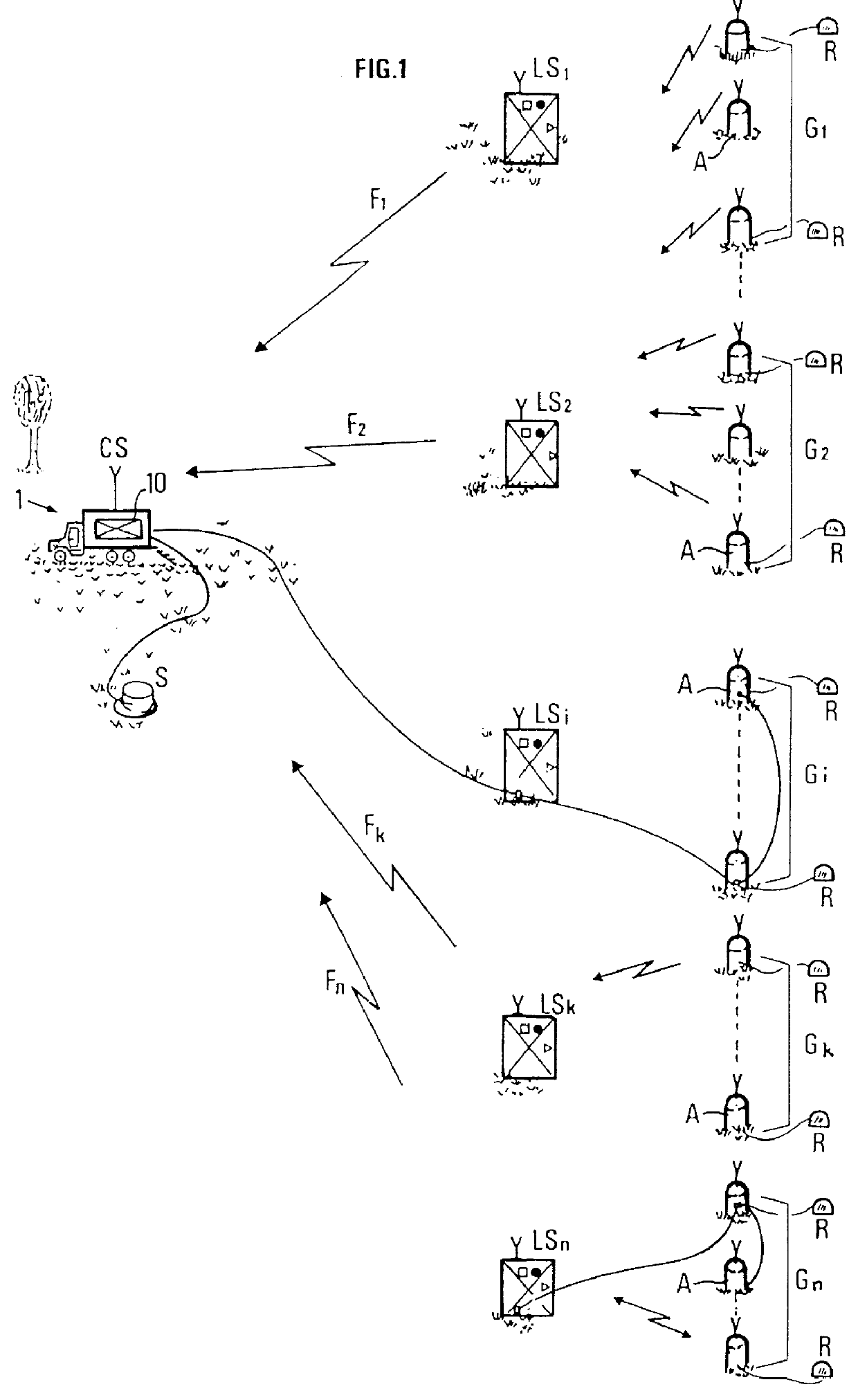
The seismic device diagrammatically shown in FIG. 1 comprises considerable number (several hundreds to several thousands) of seismic receivers R spread out at intervals in a zone to be explored, according to a layout suited to the 2D or 3D prospection type to be performed, these receivers picking up the seismic waves reflected by underground discontinuities in response to the transmission in the ground of seismic waves produced by a source S, and a remote station such as a central control and recording station 1 where all the seismic signals collected are eventually centralized by means of the transmission system described hereafter. Each one of receivers R is most often made up of a string of aligned elementary pickups which produce each a "seismic trace".
The device comprises a set of acquisition units or local seismic data collection units A, each suited for acquisition of n seismic traces (n ranging from 1 to 6 for example).
The set of acquisition units A communicates with a centr...
PUM
Abstract
The invention pertains to transmission to a remote station, by means of transmission channels (generally radio transmission channels), of seismic data acquired by a data collection equipment comprising a plurality of acquisition units, each being suited to acquire, to store and preferably to compress the data to be transmitted. The invention comprises ordered storage, in a high-capacity memory (flash type memory for example) of each acquisition unit (Ai), of data obtained during successive emission-reception cycles (acquired and possibly preprocessed seismic data) so as to form a stream of stored data to be transmitted, and progressive transfer of the stored data stream from each acquisition unit to the remote station by means of the transmission channel, by reading each storage memory, with a time lag in relation to the time of their storage depending on the transmission rate of each transmission channel and on the transmission mode selected with preferably, if sending of the data of a cycle is delayed, sending of at least partial data, compressed or not, for quality control purposes. The data transmitted are reconstituted at the remote station. The method can be used for large-scale seismic data transmission.
Description
1. Field of the InventionThe present invention relates to a method and to a system for transmitting (notably by radio waves) data to a remote station, allowing reacquiring of data acquired by a data collection equipment comprising large number of local collection stations. The method preferably uses compression techniques in order to optimize the use of available transmission channels.2. Description of the Prior ArtVarious seismic data transmission systems are used to connect local acquisition units to a central station, either directly or via intermediate stations provided complex local units concentration or control functions. The links can bc provided by cables, radio links, possibly via one or more relays, or the cable links and the radio links can be combined as mentioned for example in French Patent 2,720,518, European Patents 0,594,477 and 0,275,781, and U.S. Pat. Nos. 4,815,044, 4,979,152, 4,583,206 or 4,908,206 filed by the assignee.The assignee's European Patent 0,275,781 ...
Claims
Application Information
Patent Timeline
Application Date:The date an application was filed.
Publication Date:The date a patent or application was officially published.
First Publication Date:The earliest publication date of a patent with the same application number.
Issue Date:Publication date of the patent grant document.
PCT Entry Date:The Entry date of PCT National Phase.
Estimated Expiry Date:The statutory expiry date of a patent right according to the Patent Law, and it is the longest term of protection that the patent right can achieve without the termination of the patent right due to other reasons(Term extension factor has been taken into account ).
Invalid Date:Actual expiry date is based on effective date or publication date of legal transaction data of invalid patent.