High accuracy projectile

a projectile and high-accuracy technology, applied in the field of projectiles with improved accuracy, can solve the problems of reducing the useful life of the weapon, the disadvantage of the mpc, and the relatively high cost of the mpc, so as to improve accuracy, improve accuracy, and minimize the effect of bullet jump

Inactive Publication Date: 2000-06-06
OLIN CORP
View PDF13 Cites 245 Cited by
  • Summary
  • Abstract
  • Description
  • Claims
  • Application Information

AI Technical Summary

Benefits of technology

nd forms a gas tight seal. Another advantage of the invention is that the near tangential ogive on the fore portion of the bullet minimizes bullet jump, improving accuracy. Still another advantage of the invention is that a large frontal nose cavity shifts the center of gravity of the bullet rearward, improving accuracy. It is estimated that the hollow point accounts for about thirty-five percent improvement in accuracy over a similar design having a solid nose portion.
In accordance with the invention, there is provided a medium caliber projectile that is to be fired from a weapon having a rifled barrel. This rifled barrel has an interior bore of a first diameter and a barrel groove surface of a second diameter.
The projectile is formed from a monolithic copper alloy to have a generally circular latitudinal cross-section. The projectile has a fore portion and an aft portion with a mid-portion disposed therebetween. The fore portion extends from the nose of the projectile to a first transition plane and has arcuate sidewalls when viewed in longitudinal cross-section. These arcuate sidewalls constantly increase in latitudinal cross-sectional diameter from the nose to the first transition plane. A hollow cylindrical bore extends from an open end at the nose to a closed end proximate to the first transition plane.
The mid-portion of the projectile has a body portion of generally constant latitudinal cross-section extending from the first transition plane to a second transition plane and a drive band portion of generally constant latitudinal cross-section extending from the second transition plane to a third transition. The body has a latitudinal diameter that is effective to minimally contact the barrel rifling. The drive band has a latitudinal diameter effective to seal

Problems solved by technology

A disadvantage with the MPC is relatively high cost due to the use of a component made from tungsten carbide and the multiplicity of components within the bullet.
The projectile disclosed in U.S. Pat. No. 4,685,397 is not believed to satisfy the accuracy requirements for a 0.50 caliber match grade c

Method used


Image

  • High accuracy projectile
  • High accuracy projectile
  • High accuracy projectile

Examples


Embodiment Construction

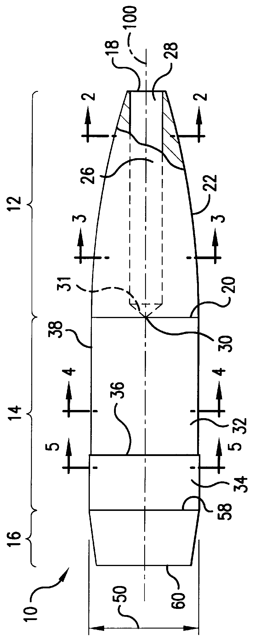
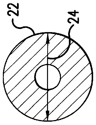
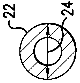
FIG. 6 illustrates the projectile of the invention illustrating dimensions, in inches, effective for a 0.50 caliber cartridge shown in FIG. 7. The cartridge is compatible with a standard 0.50 caliber (12.75.times.99 mm) application as typified by U.S. Government Chamber Drawing 5564348, the disclosure of which is incorporated herein by reference in its entirety. The cartridge may be chambered in such a weapon 80 having a chamber 82 as shown in FIG. 8. The cartridge includes a conventional bottlenecked case 60 extending from mouth at a fore end 62 to an aft end 64. At the aft end, the case includes a head 66 which contains a cap-type percussion primer 68 in a cylindrical pocket. The interior of the case contains a propellant charge 70 to propel the projectile through the barrel of the weapon when ignited by the primer. The projectile is inserted through the cartridge mouth at the fore end 62 and into the cartridge neck with the case being crimped at the fore end 62 in front of the dr...


PUM


Abstract

A projectile having improved accuracy when fired over long ranges is formed from a monolithic block of a copper alloy. Proceeding from a nose to a heel of the projectile, is a fore portion with arcuate side walls, a body portion of substantially constant cross-sectional area that minimally contacts a rifled gun barrel, a drive band having a diameter effective to seal propellant gases and an aft portion that continuously decreases in diameter terminating at the heel. A cylindrical bore extends from an opened end at the nose to a closed end proximate to a transition plane between the fore portion and the body portion.

Description

1. Field of the InventionThis invention relates to a projectile having improved accuracy. More particularly, the projectile has a hollow point, a fore portion with a near tangential ogive and an aft portion with a boattail. The projectile is machined from a monolithic block of a copper alloy.2. Description of Related ArtMedium caliber cartridges, that have a projectile diameter of between 0.3 inch and 0.6 inch, are widely used in military and sporting applications. The projectiles are often fired from a weapon over long distances, in excess of 1000 meters, and require a high degree of accuracy to hit the target. For example, the present 0.50 caliber cartridge used by the United States military for sniper applications is the grade A, MK211, multi-purpose cartridge (MPC).A disadvantage with the MPC is relatively high cost due to the use of a component made from tungsten carbide and the multiplicity of components within the bullet. There is a need for a cartridge having accuracy at lea...

Claims


Application Information

Patent Timeline
IPC IPC(8): F42B30/00F42B30/02
CPCF42B30/02F42B14/02
Inventor HALVERSON, HENRY J.
Owner OLIN CORP
Why Eureka
Try Eureka