Spring strut for vehicles

a technology of spring struts and springs, which is applied in the direction of spring/damper functional characteristics, vibration dampers, resilient suspensions, etc., can solve the problem of not realizing the predetermined damping force process

Inactive Publication Date: 2000-06-20
MANNESMANN SACHS AG
View PDF5 Cites 31 Cited by
  • Summary
  • Abstract
  • Description
  • Claims
  • Application Information

AI Technical Summary

Problems solved by technology

A disadvantage in this construction consists in that the load-dependent action of the vibration damper in particular is directly dependent on the springing force of the supporting spring, so that a predetermined desired damping force process is not realizable.

Method used


Image

  • Spring strut for vehicles
  • Spring strut for vehicles
  • Spring strut for vehicles

Examples


embodiment form

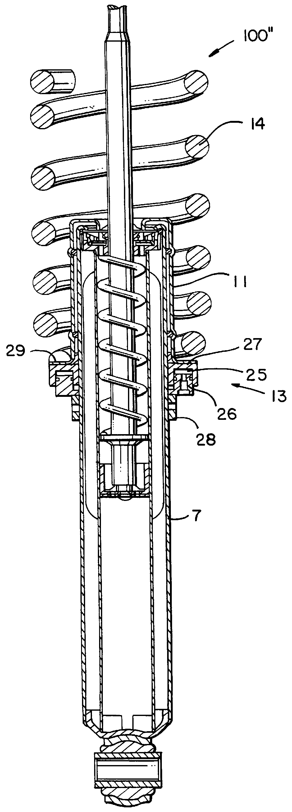
a spring strut 100" shown in FIG. 3 shows an auxiliary device 13 constructed as a pneumatic spring or a hydraulic cushion 25. The pneumatic spring or hydraulic cushion 25 comprises a ring piston 26 sealingly guided in a ring cylinder 27 is supported on a support ring 28 which is axially adjustable on container 7. A spring plate 29 of the spring carrier 11 lies on the bottom of the ring cylinder 27, while the pressure in the pneumatic spring or hydraulic cushion 25 is built up via a pneumatic or hydraulic connection located in the ring piston 26. The force of the pneumatic spring or hydraulic cushion 25 acting on the spring plate 29 in the direction opposite to the supporting spring 14 corresponds to the product of the effective cylinder surface of the pneumatic spring or hydraulic cushion 25 and its internal pressure. This enables the adaptation of the effective damping force in a simple manner which may be adjusted by a computer-controlled pneumatic or hydraulic system. Further, a ...


PUM


Abstract

The invention is directed to a spring strut for motor vehicles comprising a hydropneumatic vibration damper and a supporting spring. The vibration damper has a piston rod connected with a piston and is axially guided in a piston rod guide at the end of a container. The piston rod is outwardly sealed by a piston rod seal. The piston rod guide comprises a damping valve acted upon by external forces, such as the force of the supporting spring arranged between a structural component part connected with the vehicle and a spring carrier surrounding the container of the spring strut. The spring carrier acts on the damping valve with a contact surface. The supporting spring and/or the spring carrier cooperates with at least one auxiliary device exerting a force. The auxiliary device is supported at the container by a structural component part that is fixed with respect to the container or at a vehicle part which is connected with the container.

Description

1. Field of the InventionThe invention is directed to a spring strut, especially for motor vehicles, comprising a hydropneumatic vibration damper and a supporting spring.2. Description of the Related ArtA prior art spring strut is disclosed, for example, from DE 44 03 196 A1, wherein the vibration damper has a characteristic diagram of damping force suited to requirements. This is achieved in that the damping force characteristic diagram is formed of at least three individual force diagrams. A first damping force characteristic diagram takes effect within a middle range associated with the relatively short springing-in movement. The first damping force characteristic diagram exerts a small, preferably decreasing, damping force in response to these small spring paths. In this way, unevenness in roadways such as cobblestones which act on the vibration dampers at higher frequencies are damped to a lesser degree.This first damping force diagram passes into another damping force diagram ...

Claims


Application Information

Patent Timeline
Patent Type & Authority Patents(United States)
IPC IPC(8): B60G17/027B60G15/06B60G15/00B60G17/02B60G15/12F16F1/02F16F9/32F16F1/32F16F9/58F16F9/36
CPCB60G15/065B60G15/12B60G17/0272F16F9/3242F16F9/362F16F9/585F16F1/322F16F2228/06
Inventor GRUNDEI, MANFRED
Owner MANNESMANN SACHS AG
Why Eureka
Try Eureka