Torsional damper for watercraft propulsion system

a technology of torsional dampers and watercraft, which is applied in the direction of marine propulsion, special-purpose vessels, vessel construction, etc., can solve the problems of affecting the rider, prone to internal vibration problems, and torsional vibration is more noticeabl

Inactive Publication Date: 2000-06-20
YAMAHA MOTOR CO LTD
View PDF12 Cites 26 Cited by
  • Summary
  • Abstract
  • Description
  • Claims
  • Application Information

AI Technical Summary

Problems solved by technology

Such engines, however, can be prone to internal vibrational problems.
Torsional vibration is more noticeable at certain speeds and can be irritating to the rider.
Such vibrations may also damage the crankshaft.
Such stresses can cause failure under some conditions.
Prior watercraft propulsion systems have not adequately isolated the watercraft hull from such vibration, nor have they included a suitable mechanism to shift the severity of the resulting resonance.

Method used


Image

  • Torsional damper for watercraft propulsion system
  • Torsional damper for watercraft propulsion system
  • Torsional damper for watercraft propulsion system

Examples


Embodiment Construction

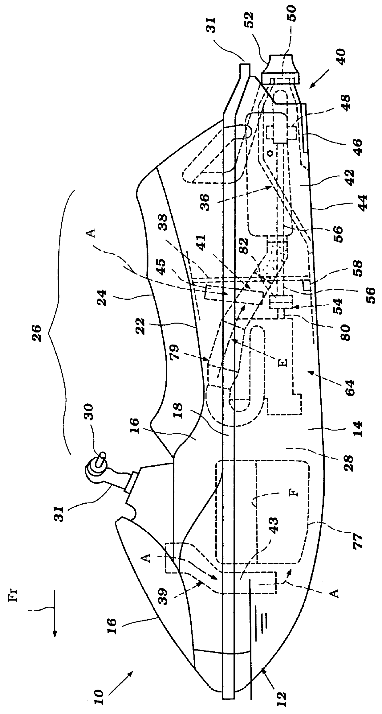
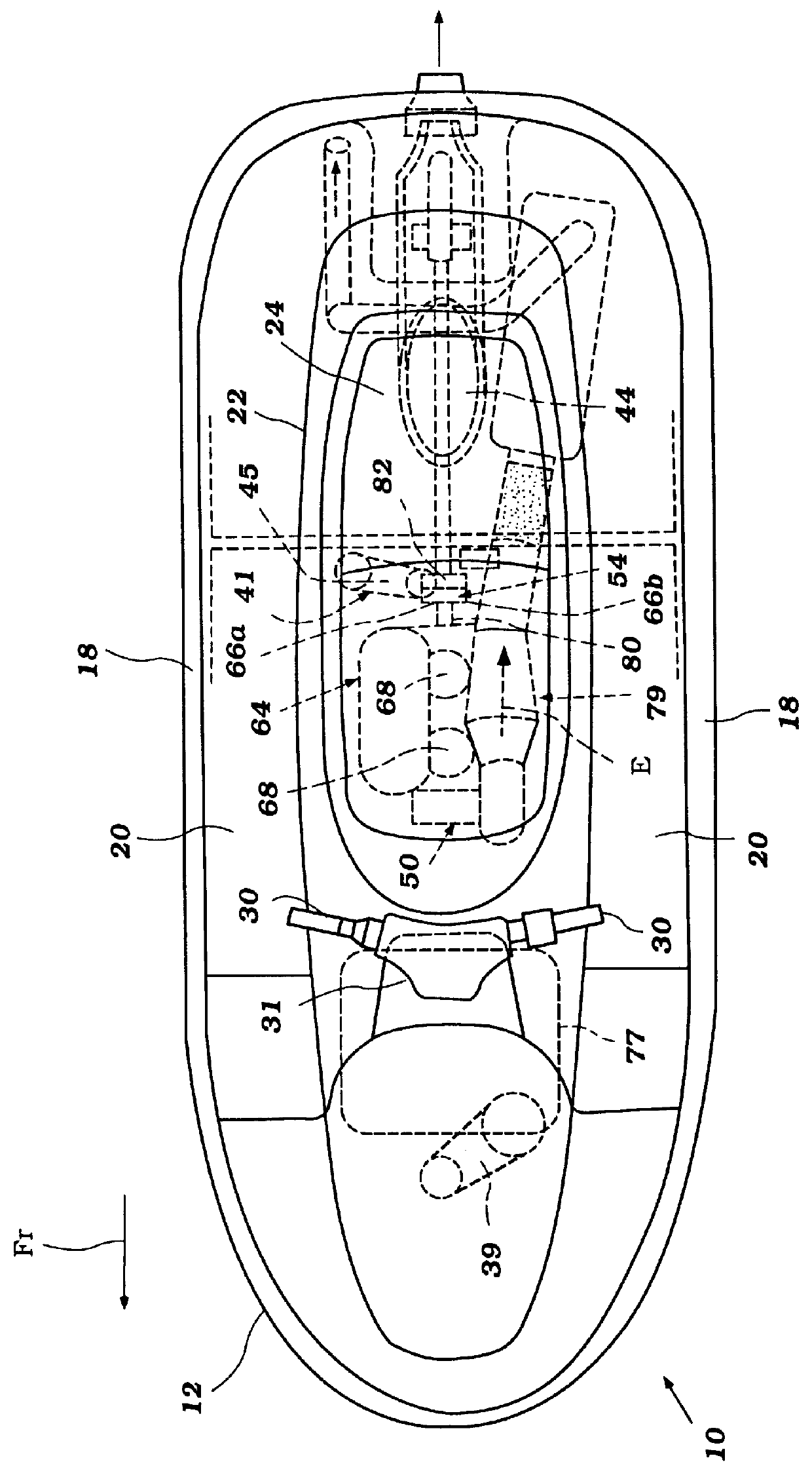
The present torsional damping mechanism has particular utility for use with a propulsion system of a personal watercraft, and thus, the following describes the damping mechanism in the context of a personal watercraft. This environment of use, however, is merely exemplary. The present torsional damping mechanism can be readily adapted by those skilled in the art for use with other types of watercraft, including, but without limitation, small jet boats and the like.

With initial reference to FIGS. 1 and 2, the watercraft 10 includes a hull 12 that is formed by a lower hull section 14 and an upper deck section 16. The hull sections 14, 16 are formed of a suitable material such as, for example, a molded fiberglass reinforced resin, and can be made by any of a wide variety of methods. For instance, the deck 16 and the hull 14 can each be formed using a sheet molding compound (SMC), i.e., a mixed mass of reinforced fiber and thermal setting resin, that is processed in a pressurized, close...


PUM


Abstract

A vibrational damper reduces torsional vibration within a crankshaft of a marine engine. The vibrational damper is located on an end of the crankshaft opposite of the flywheel and includes an inertia ring that adds additional mass to this opposite end. In addition, the vibrational damper includes an elastic member that suspends the inertia ring about the crankshaft. The elastic member effectively dampens torsional vibrations. The torsional damper desirably is cooled by an air flow so as to maintain it's dampening efficiency. A ventilation duct, which is positioned directly above the vibrational damper, supplies the cooling air. Cooling is enhanced by locating a bilge system inlet below and slightly behind the vibrational damper. An air flow stream occurs between the duct and the bilge inlet and across the torsional damper to cool the torsional damper.

Description

1. Field of the InventionThe present invention relates in general to a vibration reduction mechanism, and in particular to a torsional damper for use in the propulsion system for a watercraft.2. Description of Related ArtIn many propulsion systems that propel small watercraft, such as personal watercraft and small jet boats, an internal combustion engine drives a jet propulsion unit. For this purpose, a flexible coupling often couples an output shaft of the engine to the impeller shaft of a jet pump unit. The impeller shaft in turn drives a propulsion device, such as an impeller within the jet pump unit.The propulsion systems of most small watercraft today use two or three cylinder engines. Such engines, however, can be prone to internal vibrational problems. For instance, the explosive forces acting on the pistons and the inertia forces of the moving parts vary in intensity as the pistons of the engine reciprocate. The resulting variation of force or torque on the crankshaft causes...

Claims


Application Information

Patent Timeline
Patent Type & Authority Patents(United States)
IPC IPC(8): B63J2/00B63J2/06B63B13/00F01P1/06F01P1/00F02B61/00F16F15/10F16F15/14F02B61/04B63H1/15
CPCB63B13/00B63J2/06F16F15/1442F02B61/045F01P1/06F01P2050/02
Inventor ITO, KAZUMASA
Owner YAMAHA MOTOR CO LTD
Why Eureka
Try Eureka