Tissue punching instrument

Inactive Publication Date: 2000-06-27
IDX MEDICAL
View PDF4 Cites 209 Cited by
  • Summary
  • Abstract
  • Description
  • Claims
  • Application Information

AI Technical Summary

Benefits of technology

It is a main object of the present invention to provide a surgical tissue pu

Problems solved by technology

Disposal of debris is yet another problem with known punches.
Should a piece of tissue fall back inside the aorta it will be carried away by the patient's blood circulation and may result in an obstruction of a vessel.
This process (embolization) can be fatal or can cause serious damage to a patient, particularly if the debris obstructs a cerebral (stroke) or coronary (heart attack) vessel.
This cleaning process is time consuming and can lead to errors.
While attempts have been made to produce a self-cl

Method used


Image

  • Tissue punching instrument
  • Tissue punching instrument
  • Tissue punching instrument

Examples


Embodiment Construction

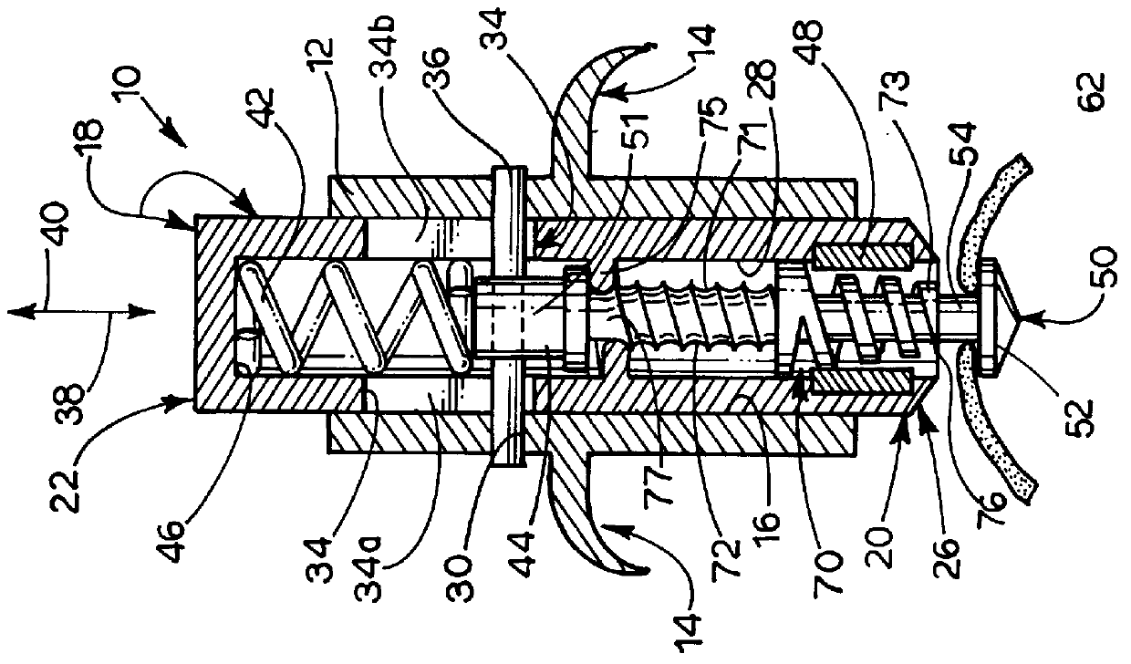
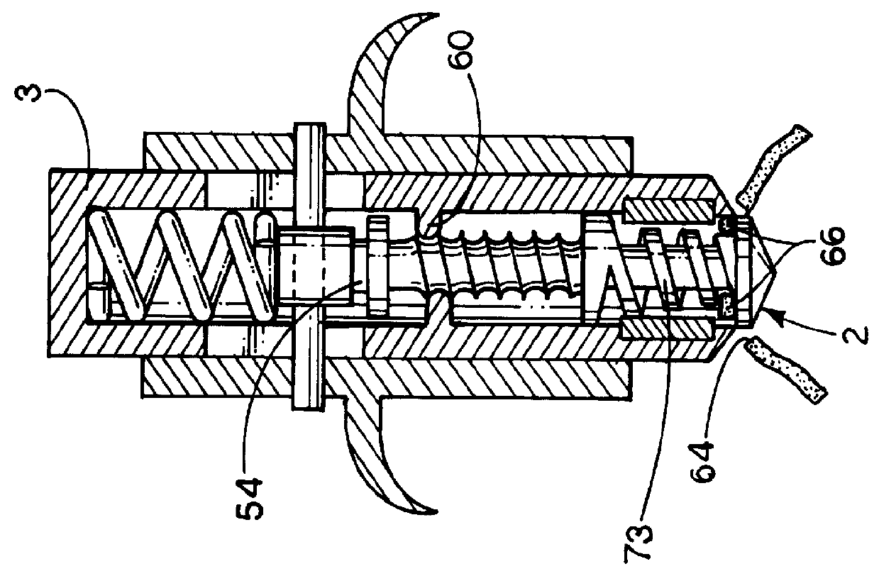
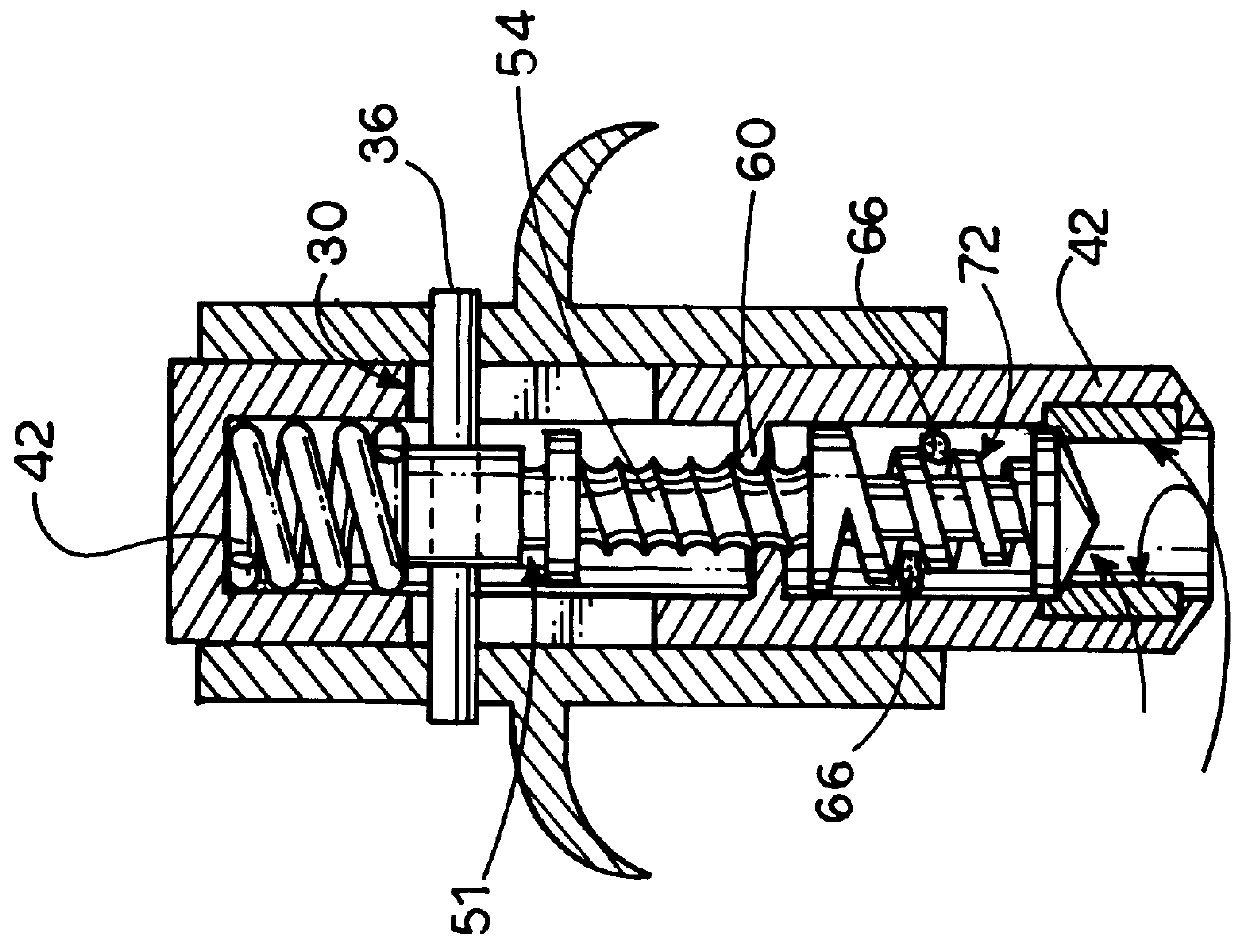
Shown in FIGS. 1-4 is a tissue punch 10 forming a first form of the device of the present invention. Punch 10 includes an outer body 12 which is cylindrical and includes a finger-engaging element 14. Outer body 12 is hollow and includes a central bore 16 in which cylindrical plunger body 18 is slidably located. Plunger body 18 includes a distal end 20 and a proximal end 22 on which a surgeon places his or her thumb during operation of punch 10. A tissue cutting edge 26 is formed on the distal end of plunger body 18 and the plunger body is hollow with a central bore 28 extending from distal end 20 to proximal end 22. A transverse bore 30 is defined in the wall of housing 12 and a cutout 34 is defined on diametrically opposite sides of plunger body 18 to define openings 34a and 34b shown in FIG. 1. A cross pin 36 is mounted on outer housing 12 and extends through openings 34a and 34b. Cross pin 36 is stationary with respect to outer housing 12 with plunger body 18 being movable with r...


PUM


Abstract

A surgical punch prevents tissue debris associated with punching a hole in a patient's tissue, such as an aorta during an anastomosis procedure, from reentering the patient's bloodstream. The punch includes elements that move the debris away from the cutting site and then capture that debris inside the instrument. The punch also includes means for aligning the punch with the selected site and for atraumatically holding the tissue prior to cutting. Various means for moving the tissue debris and for trapping the tissue debris in the instrument are also disclosed.

Description

The present invention relates to the general art of surgery, and to the particular field of surgical devices, including tissue punches.Coronary bypass surgery is frequently performed in the treatment of coronary artery disease. When native coronary arteries are obstructed (coronary artery disease) bypasses can be created by shunting flow from a large vessel such as the aorta to a part of the obstructed blood vessel downstream of the obstruction. As is known in this art, a variety of conduits (tubes) can be used to carry this bypass flow, including portions of the patient's own arteries and veins or artificial materials. Co-pending patent application Ser. No. 08 / 200,615 filed on Nov. 27, 1998 and U.S. Pat. No. 5,868,763, the disclosures of which are fully incorporated herein by reference, disclose means and methods for performing an anastomosis which can be used in such bypass surgery.When a conduit is connected to the aorta (anastomosed) the process is initiated by defining an incis...

Claims


Application Information

Patent Timeline
IPC IPC(8): A61B17/32A61B17/11A61B17/03
CPCA61B17/32053A61B2017/1107
Inventor WILLIAMSON, IV, WARREN P.BERKY, CRAIG B.SPENCE, PAUL A.ORTIZ, MARK
Owner IDX MEDICAL
Why Eureka
Try Eureka