Floor cleaning machine and method

a floor cleaning and floor technology, applied in the field of floor cleaning machines, can solve the problems of inability to adapt the power unit easily, inhibit the possibility of the floor cleaner tipping forward,

Inactive Publication Date: 2000-07-18
BREUER ELECTRIC MFG
View PDF10 Cites 104 Cited by
  • Summary
  • Abstract
  • Description
  • Claims
  • Application Information

AI Technical Summary

Problems solved by technology

In addition, there is no hint in the subject patent that its power unit can be adapted readily for various floor carpet cleaning modes.
An additional problem is to address the construction of a floor scrubber or

Method used


Image

  • Floor cleaning machine and method
  • Floor cleaning machine and method
  • Floor cleaning machine and method

Examples


Embodiment Construction

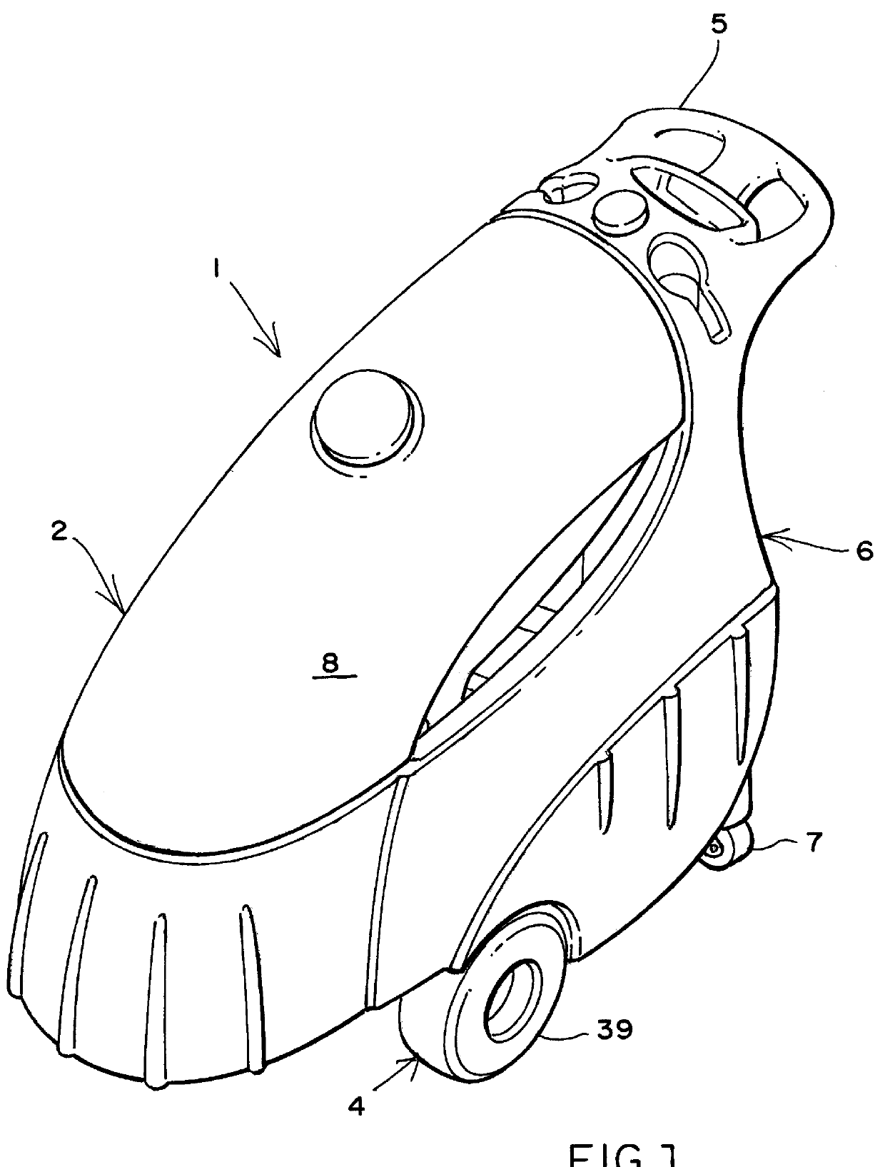
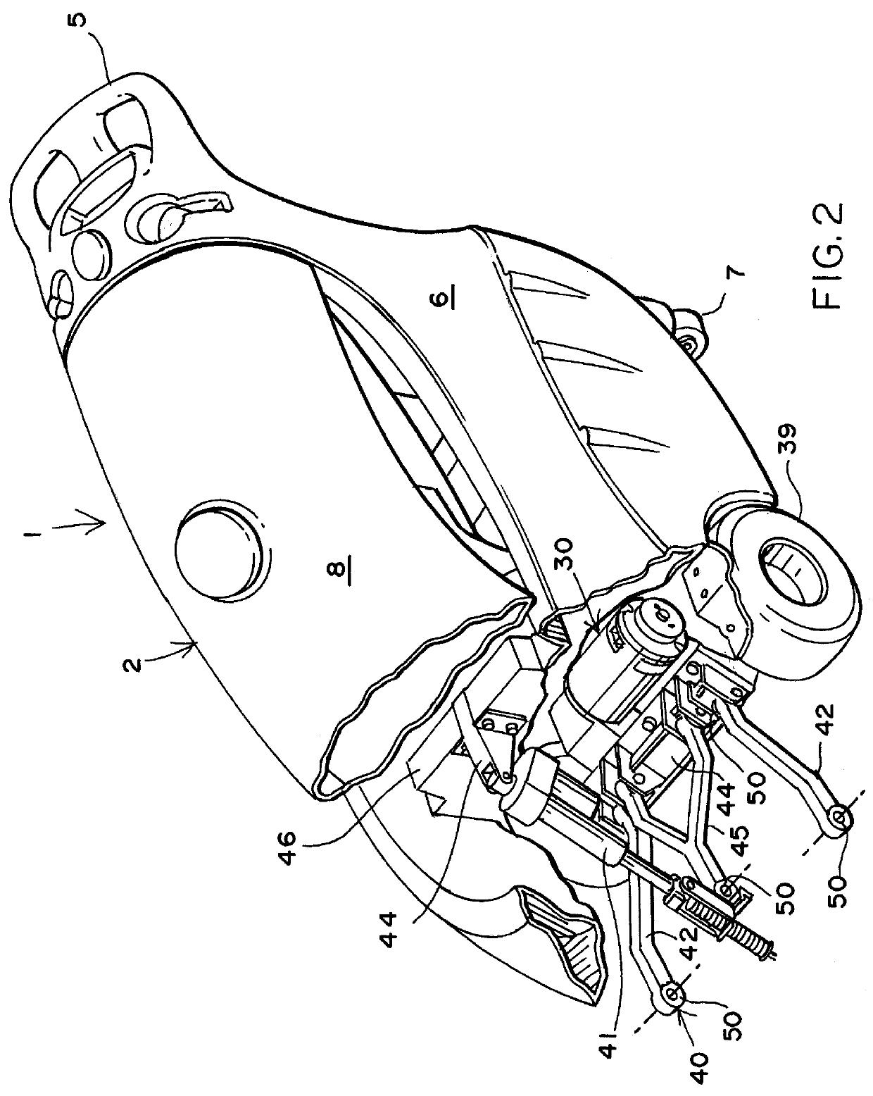
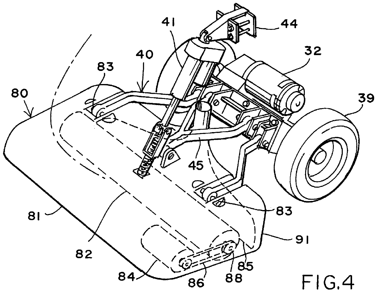
As stated above, the invention is directed to a floor cleaning machine 1 such as that illustrated in FIG. 1. The floor cleaning machine has as its principal element a hollow body portion 2. The entire hollow body portion is supported by a wheel assembly, such as that illustrated in FIG. 8. Two wheels 39 are secured to a trans-axle power drive 30 which, in turn, is secured to the lower body assembly 6. The casters 7 are secured to the under portion of the lower body assembly 6 at the rear of the lower body assembly 6. The power unit is controlled and maneuvered by the handle 5 positioned above the casters 7. The body cover assembly 8 is hollow to contain the recovery fluid. Similarly, the lower body assembly 6 is also hollow to contain the cleaning solution. Hence, the overall body 2 is made up primarily of two hollow fluid retention members, one of which retains the clean water or cleaning solution, and the other of which carries the recovered fluid. Batteries 65 for driving all pro...


PUM


Abstract

A floor cleaning machine having a body in which the body cover assembly is hollow and serves as the recovery solution reservoir; while the lower body assembly, which is also hollow, serves as the cleaning solution tank or reservoir. In addition, the lower body has a recessed area proportioned to receive and secure the batteries required for driving the motors involved in the floor cleaning machine. A trans-axle drive supports the lower body and has a drive wheel at each end powered by a motor differential engaging the axles coupled to the wheels. Together the body and trans-axle drive comprise a modular power unit. Mounting means are provided on the forward portion of the lower body of the power unit for lift arms to be secured to various power floor scrubbers for use on hard floors or a carpet extractor for cleaning carpeted floors. The linkage for the floor scrubber mode and carpet cleaning mode is the same. Such linkage also uses a maximum number of resiliently mounted bushings which, along with the monocoque body and retained fluid movement, cushion against damage by impact under power.

Description

The subject matter of this invention is directed to a floor cleaning machine. More particularly it relates to a floor cleaning machine which has a cleaning solution tank, a recovery tank, a battery compartment, power supply, and means for accepting a floor scrubbing heads for various hard surface floors, or even a carpet cleaning head for carpeted floors.SUMMARY OF THE PRIOR ARTCommercial floor scrubbing machines are known in the industry. Most such machines have dedicated rotating brushes and fluid dispensing means for cleaning either hard floors or carpeted floors. Such machines are usually selfpropelled by battery driven electric motors. Exemplary of such a machine is recently issued U.S. Pat. No. 5,611,105, issued Mar. 18, 1997. This patent discloses a floor scrubbing machine. The disclosure is particularly directed to its asserted ability to resist impact by hoisting itself into the air when colliding with a wall or other obstacle. It should be noted that the scrubber taught in...

Claims


Application Information

Patent Timeline
IPC IPC(8): A47L11/00A47L11/30A47L11/40A47L11/29
CPCA47L11/302A47L11/4016A47L11/4041A47L11/4044A47L11/4058A47L11/4072A47L11/4088
Inventor PACCHINI, DAVIDPOTTER, MATTHEW B.
Owner BREUER ELECTRIC MFG
Why Eureka
Try Eureka