Eureka AIR delivers breakthrough ideas for toughest innovation challenges, trusted by R&D personnel around the world.

Exhaust gas filtering process and unit with modulable heating

Inactive Publication Date: 2000-07-18
INST FR DU PETROLE
View PDF11 Cites 90 Cited by
  • Summary
  • Abstract
  • Description
  • Claims
  • Application Information

AI Technical Summary

Benefits of technology

The present invention allows improved operation of a particulate filter which provides energy saving as well as reliability.
The intelligent regeneration management of the present invention limits risks of degradation of the filtering element linked with excessive heat release.

Problems solved by technology

By that time, improvements linked with engines and fuels may be insufficient, even in the presence of an oxidation catalytic muffler, especially for the soluble part of the particulate emitted.
The technical difficulty encountered for developping such a system lies in that the filter must be periodically regenerated by combustion of the soot deposit.
However, average running conditions generally lead to temperatures that are too low to spontaneously initiate combustion of the particulates.
This leads to clogging of the filter, which is inconvenient for the engine efficiency and eventually threatens the running thereof It is then necessary to provide artificial regeneration of the filter.
However, for certain driving modes, problems linked with the back pressure can subsist, so that an external energy supply such as electric heating can be necessary.
This leads to a controlled high power consumption.
Generally, the electrical power required to initiate total regeneration of the filter is high and often not compatible with the electrical resources on board the vehicle.
Furthermore, the regeneration conditions can highly depend on the fouling condition of the filter.
The well-known electric heaters do not allow action according to the fouling of the filter.

Method used


Image

  • Exhaust gas filtering process and unit with modulable heating
  • Exhaust gas filtering process and unit with modulable heating
  • Exhaust gas filtering process and unit with modulable heating

Examples


Embodiment Construction

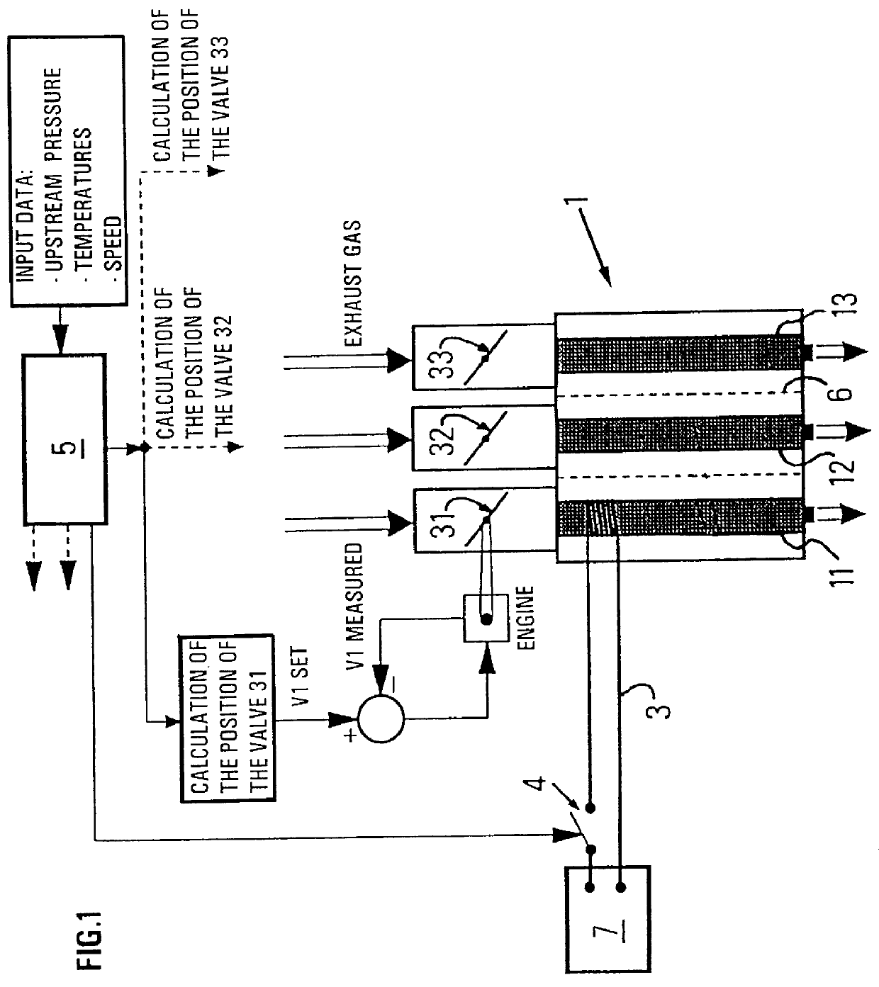
In FIG. 1, a filtering set 1 commonly referred to as particulate filter is placed on the path of the exhaust gases whose flow is shown by double arrows. Filtering set 1 comprises several filtering elements 11, 12, 13 consisting for example of filtering cartridges marketed by the the 3M company.

Structure such as partitions 6 can be provided to divide filtering set 1 and to isolate the various filtering elements 11, 12, 13.

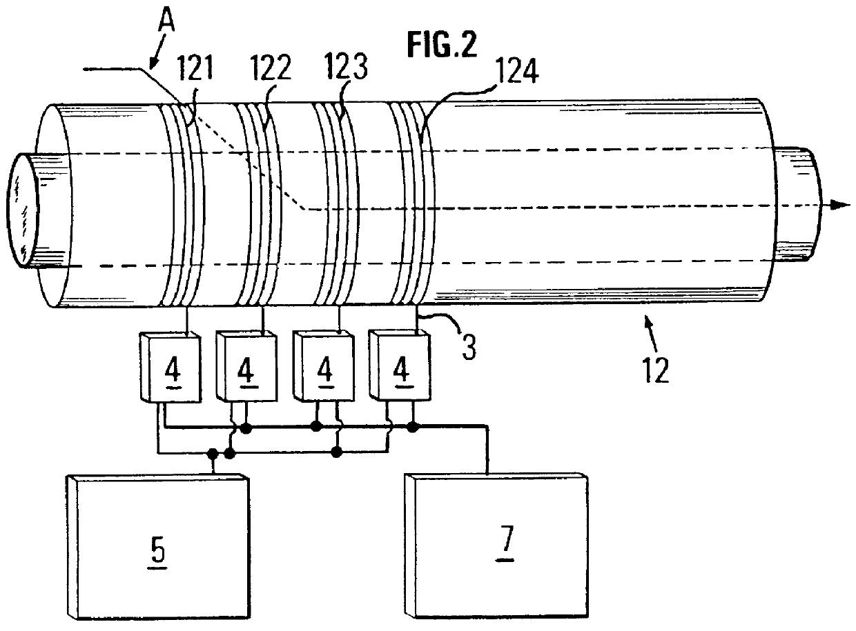
A filtering element 12 is shown in FIG. 2. This element is equipped here with several resistive elements 3, each one heating a zone 121, 122, 123, 124 of filtering element 12. More precisely, the resistor is a spiral wire wound around a filtering cartridge 12.

According to the simple embodiment of the invention, a single resistive wire 3 is wound around a zone 121 of a filtering element such as 12.

Without departing from the scope of the invention, a single zone can also be thus equipped in each filtering element.

FIG. 2, which will be commented on hereafter, allows de...


PUM

PropertyMeasurementUnit
Temperatureaaaaaaaaaa
Poweraaaaaaaaaa
Accelerationaaaaaaaaaa

Abstract

The present invention is a filtering unit providing after-treatment of the gases emited in the exhaust of Diesel engines, comprising a filtering set which includes at least one filtering element (11, 12, 13); at least one resistive element (3) which heats a zone (121, 122, 123) of one of the at least one filtering element; at least one detection device which determines fouling of the filtering set (1); a control (5), responsive to the at least one detection device, which controls independently each of the resistive elements, according to the fouling of the filtering set and electrical power available to the at least one resistive element. The resistive elements (3) can be each wound around a zone of a filtering element. The invention further relates to the associated process.

Description

1. Field of the InventionThe present invention relates to the after-treatment of gases emitted in the exhaust of Diesel vehicles.2. Description of the Prior ArtParticulate emission standards have recently come into effect in Europe. These standards will become more stringent in the coming years. By that time, improvements linked with engines and fuels may be insufficient, even in the presence of an oxidation catalytic muffler, especially for the soluble part of the particulate emitted.Particulate filters are a well-known exhaust gas after-treatment technique. It is thus possible to obtain filtration efficiencies above 80%. Many filter technologies have been developed to date. Examples thereof are the ceramic monolith marketed by the Coming Company, or the cartridge with coiled ceramic fibers as described in patent application WO-95 / 127,843.The technical difficulty encountered for developping such a system lies in that the filter must be periodically regenerated by combustion of the ...

Claims


Application Information

Patent Timeline
IPC IPC(8): B01D46/24F01N3/023F01N3/027F01N3/031F01N3/032F01N9/00F02B3/06F02B3/00B01D46/00F01N3/02B01D46/44
CPCB01D46/0063B01D46/448F01N3/0235F01N3/027F01N3/032F01N9/002B01D2279/30F02B3/06Y02T10/47Y10S55/30Y10S55/10Y02T10/40B01D46/84
Inventor DEMENTHON, JEAN-BAPTISTEMARTIN, BRIGITTEPAJOT, OLIVIER
Owner INST FR DU PETROLE
Why Eureka
Eureka Blog
Learn More