Self-centering rotor bearing assembly for submersible pump motors

a rotor bearing and motor technology, applied in the direction of positive displacement liquid engines, piston pumps, liquid fuel engines, etc., can solve the problems of axial mobility, difficulty in axial mobility, and long system length

Inactive Publication Date: 2000-07-18
CAMCO INT
View PDF25 Cites 84 Cited by
  • Summary
  • Abstract
  • Description
  • Claims
  • Application Information

AI Technical Summary

Problems solved by technology

Accordingly, the motors of submersible pumping systems can be quite long leading to particular difficulties not encountered in other electric motor applications.
Due to these thermal expansion effects, the motor is constructed so that each rotor bearing assembly attached to the motor shaft within a rotor section offers a limited amount of axial mobility.
Thus, because each rotor bearing assembly is coupled to the motor shaft, the shaft retains the same limited amount of axial mobility.
Axial mobility is limited by thrust washers adjacent to each rotor bearing assembly.
Angular misalignment of the shaft within the motor can occur because the rotor, shaft, and stator are subject to these dimensional changes due to thermal expansion and because of imbalances in the rotating assembly.
Misalignment of the shaft during operation opposes the centering, or aligning force of the bearing assembly and causes vibrations within the motor.
Excess vibration can lead to premature motor or component failure.
Such metal-to-metal frictional fit rotor bearing assemblies have a tendency to become loose and then to rotate with the shaft.
Rotation of the journal

Method used


Image

  • Self-centering rotor bearing assembly for submersible pump motors
  • Self-centering rotor bearing assembly for submersible pump motors
  • Self-centering rotor bearing assembly for submersible pump motors

Examples


Embodiment Construction

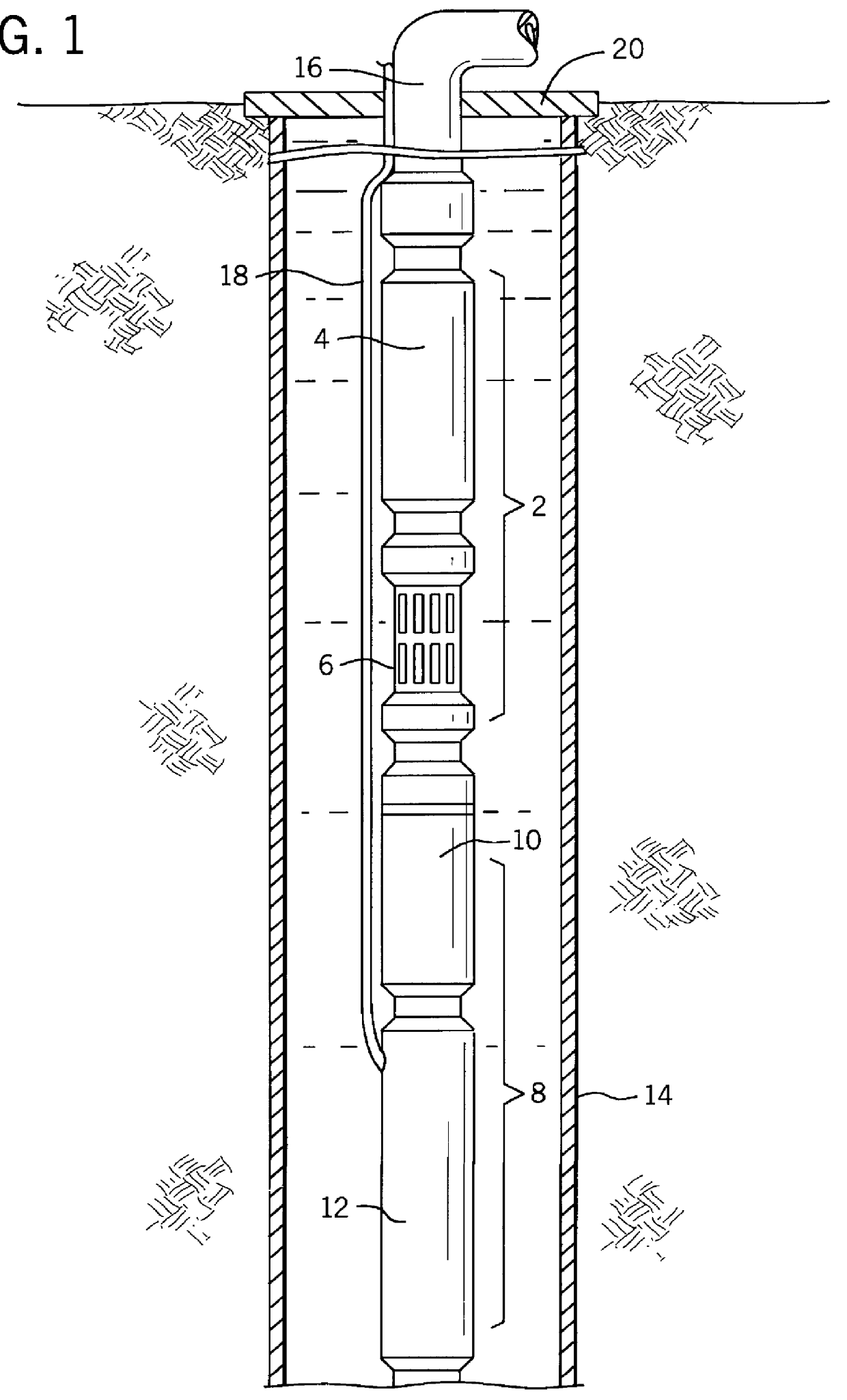
Referring to FIG. 1, a submersible pumping system is depicted as including a pump module and a motor module. Pump module 2 is comprised of a pump 4 and an inducer or intake section 6 for the pump. Motor module 8 is comprised of a motor protector 10 and a motor 12. The pump module and the motor module are coupled to one another and disposed colinearly within the well casing 14 and suspended at an appropriate position within well casing 14 by tubing 16. Electrical power is provided to the motor by means of a power cable 18. The fluid of interest to be pumped from the well by means of the submersible pumping system is produced to the surface through tubing 16 and through well head 20.

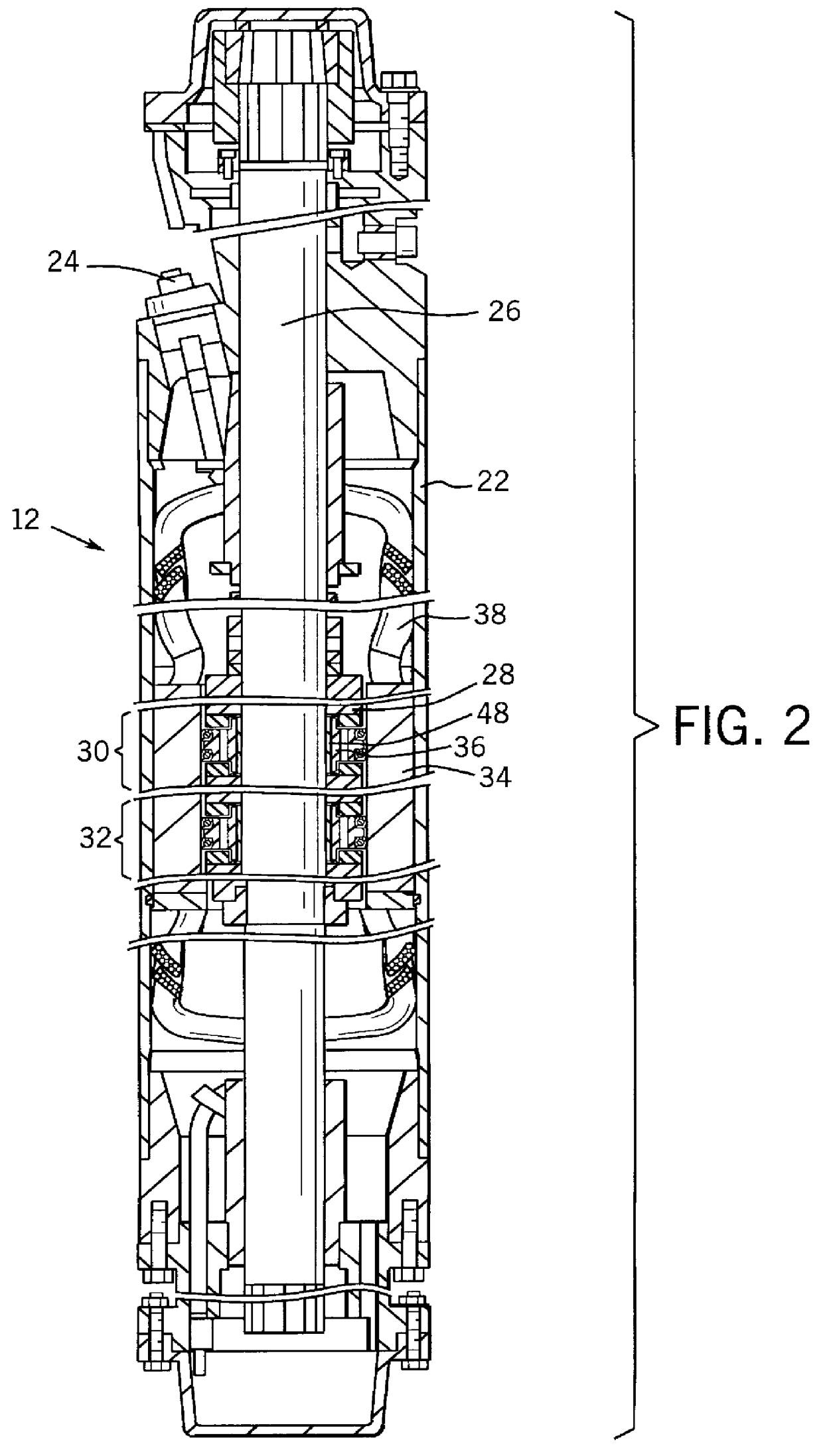
FIG. 2 illustrates a submersible pump motor 12 in accordance with the present invention. The motor is contained within a housing 22 into which an electrical connector 24 penetrates for transmitting power from cable 18 (See FIG. 1). The motor is comprised primarily of a rotating group and a non-rotating gro...


PUM


Abstract

The invention provides a submersible pumping system which includes a motor containing self-centering rotor bearing assemblies. Each rotor bearing assembly in accordance with the present invention includes a sleeve, a journal, and at least two seals. The journal is preferably disposed about the sleeve which is keyed to the power transmission shaft of the motor. The journal has a peripheral surface which is configured to have at least two circumferential support regions which are spaced apart from one another. Each of these circumferential support regions supports a corresponding seal. Each seal includes an interface member and an activating member. When in place in a rotor section of a submersible pump motor, the seals frictionally engage the inner surface of the stator and exert a centering force against the journal and thus against the bearing sleeve and the power transmission shaft. The seals also exert a force against the inner surface of the stator which prevents rotation of the journal when the power transmission shaft is rotating.

Description

1. Field of the InventionThis invention relates generally to submersible pump motors, and in particular to the rotor bearings used therein.2. Discussion of the Related ArtSubmersible pumping systems have been employed in the pumping of oil and water from wells for many years. Typically, a submersible pumping system comprises an electric motor, a motor protector, and a pump suspended colinearly in a well casing by tubing or cable. The pump is generally a centrifugal pump which is coupled to the motor. The motor rotates a power transmission shaft that concurrently operates the pump. The motor and motor protector are filled with oil to aid in heat dissipation, to maintain proper internal lubrication of the motor, and to separate the internal components of the motor from surrounding wellbore fluids.Because these pumping systems are generally disposed within a narrow well casing, the motor, motor protector, and pump are generally long and cylindrically shaped. The motors vary in horsepow...

Claims


Application Information

Patent Timeline
IPC IPC(8): F16C27/06F16C27/00F16C17/00F16C17/22
CPCF16C17/22F16C27/063F04D13/10F04D29/047
Inventor KINSINGER, GRIFF H.
Owner CAMCO INT
Why Eureka
Try Eureka