Curl and profile correction with high velocity hoods

a profile correction and high-speed technology, applied in drying machines, drying, light and heating equipment, etc., can solve the problems of inability to use "dry air" and extremely energy-intensive use, and achieve the effect of reducing the force which results in curling

a profile correction and high-speed technology, applied in drying machines, drying, light and heating equipment, etc., can solve the problems of inability to use "dry air" and extremely energy-intensive use, and achieve the effect of reducing the force which results in curling

US6094838AInactive Publication Date: 2000-08-01ASEA BROWN BOVERI INC

Image

  • Curl and profile correction with high velocity hoods
  • Curl and profile correction with high velocity hoods
  • Curl and profile correction with high velocity hoods

Examples


Embodiment Construction

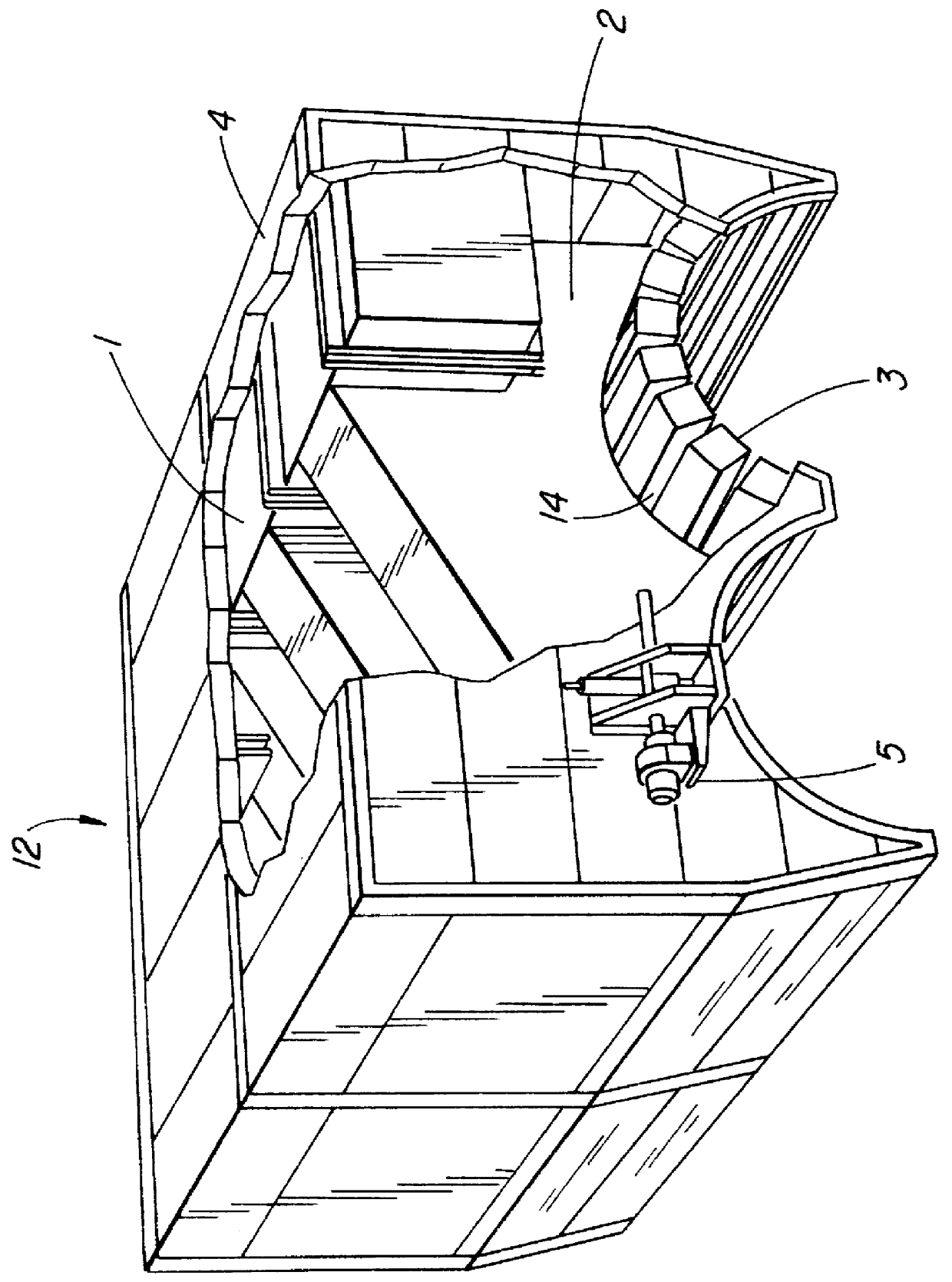
Referring to FIG. 1, hot drying air is supplied to the hood 12 from a system of ducts with a circulating fan, heating system (either steam heating coils or burner) not shown here. Alternatively, the hood can be supplied with internally mounted fans and burners or coils and in that way reduce the amount of space required for external ducting. One form of hood is described in Applicant's U.S. Pat. No. 5,531,033 issued Jul. 2, 1996, "Controlled Profile Drying Hood". See also Applicant's U.S. Pat. No. 5,784,804 "Yankee Hood with Integral Air Heating System".

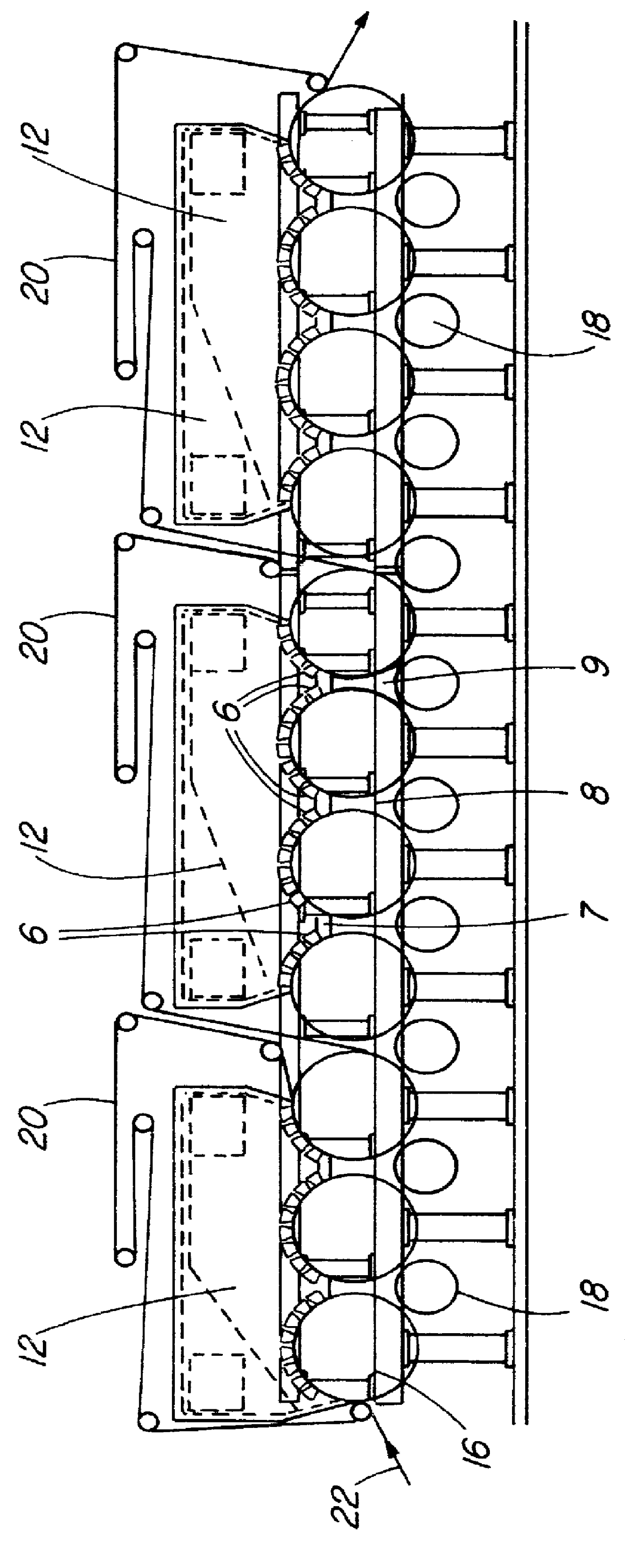
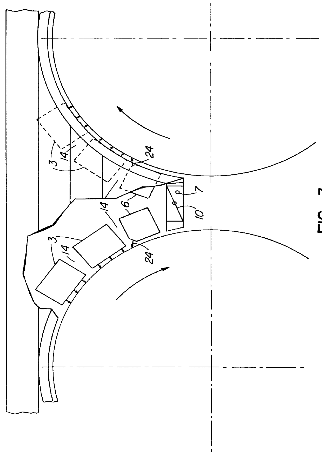
The air enters the supply header 1 and is delivered through a plurality of distribution headers 2 to nozzle boxes 3, having a rectangular cross section, and which run transverse to the web and are arrayed around the perimeter of the dryer cylinder, generally between 90 and 240 degrees as shown in FIG. 2. The front face of the nozzle boxes are perforated, whereby the impinging drying air blows onto the paper web. The gap 14 between ad...


PUM


Abstract

A method and apparatus for correcting the curl in drying and dried paper is presented wherein high velocity hoods are used in combination with drying cylinders. In addition, the use of impingement drying hoods provide a means to correct for variations in the moisture profile of the paper. High velocity hoods can be located in the drying section of a paper machine to compensate for uneven drying by paper cylinders.

Description

This invention relates to paper drying and in particular to a method and apparatus to be used in the drying section of a paper machine to reduce curl in the finished product.A dryer section of a paper machine receives a paper web to be dried, from the forming end and pressing section of the paper machine. The web is conventionally dried on a plurality of dryer rolls heated by steam or gas so as to reduce the moisture content of the web to an acceptable percentage. The moving paper web travels over and with the drying cylinders which, conventionally, have been arranged in two tiers with one side of the web contacting one cylinder and then the other side of the web contacting the next cylinder.In recent times, drying sections of paper machines have the drying cylinders grouped entirely or largely in single tiered sections with all or most of the drying being done or one side of the web only. This can cause uneven or one sided drying of the web which can lead to a bowing or curl of the...

Claims


Application Information

Patent Timeline
01 Aug 2000
Publication
US6094838A
IPC
D21F5/00; D21F5/04
CPC
D21F5/044
Inventors
LANG, IAN G.