Starter for an internal combustion engine

a technology for starting units and internal combustion engines, which is applied to engine starters, combustion engines, electric motor starters, etc., can solve the problems of unambiguously oversized starter generators, inability to use starter generators with a typical 12 space,

Inactive Publication Date: 2000-08-08
ROBERT BOSCH GMBH
View PDF8 Cites 93 Cited by
  • Summary
  • Abstract
  • Description
  • Claims
  • Application Information

AI Technical Summary

Problems solved by technology

Such a design, because of the relatively brief attainable total service life of the starter motor and in particular its pinion, its toothed ring, and its override clutch, as well as for noise reasons no longer leads to an embodiment with a promising future.
Because of the necessary starting energy and starting power (approximately 150 Nm to 200 Nm of cold-starting torque for a medium-priced automobile) it is not feasible to use a starter generator with a typical 12 to 24 V lead starter battery.
Furthermore, the electric motor of the starter-generator would have to be enlarged by more than a factor of 3 compared with what is needed for the generator power, which among other effects would also lead to problems in terms of space.
For starting an engine at operating temperature, such a starter-generator would be unambiguously oversized.
If the automatic inertia utilization transmission turns on frequently, still other problems arise in supplying the on-board electrical system.
For re-starts, however, of the kind done with the engine warm at a traffic light or at the end of an overrunning phase, it is unfavorable because of the time needed.
The same problem also exists in a design of the kind described in German Patent Disclosure DE 29 17 139.
Overall, until now, in a crankshaft starter-generator concept, either an excessively high starting moment for the cold start, as a direct start system, was definitive for designing the electrical machine and various other electrical components, so that overall an appropriate compromise would not be found, or if a classical starter or an impulse starter was used, the demands for the re-starting with regard to starting time, low noise level, wear and service life, for the high demanded number of 400,000 cycles and more, could not all be attained.

Method used


Image

  • Starter for an internal combustion engine
  • Starter for an internal combustion engine

Examples


Embodiment Construction

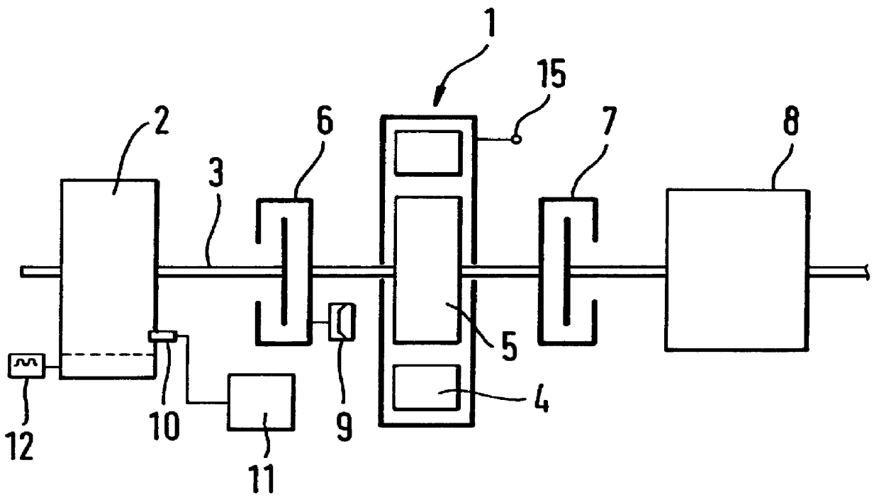
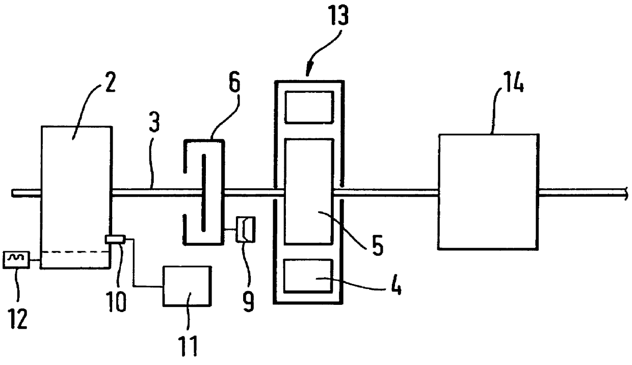
A starter unit 1 for an internal combustion engine 2 engages a crankshaft 3 (drive shaft) and has a flywheel starter-generator 4, 5 with an electrical machine, not shown in further detail, comprising a stator and a rotor. Between the engine 2 and the flywheel starter-generator 4, 5, a first (normal) clutch 6 is provided. A second clutch 7 (drive clutch) is located between the flywheel starter-generator 4, 5 and a manual transmission 8. The clutch 6 is equipped with a fast-closing servo 9.

A temperature sensor 10 is mounted on the engine 2 and reports the current temperature to an electrical or electronic changeover device 11. The changeover device 11 sends temperature-dependent commands to the starter-generator 4, in order to set it either for direct starting or alternative starting (impulse starting) with flywheel energy. A latent heat store 12 may be provided on the engine 2, to preheat the motor oil.

The alternative start is undertaken with the engine stopped, when its temperature ...


PUM


Abstract

PCT No. PCT/DE97/01663 Sec. 371 Date Sep. 22, 1998 Sec. 102(e) Date Sep. 22, 1998 PCT Filed Aug. 7, 1997 PCT Pub. No. WO98/20252 PCT Pub. Date May 14, 1998The starter apparatus for an internal combustion engine (2) includes a starter-generator including a device for rotating a flywheel (5) to a predetermined rotational speed and a device for rotating the crankshaft (3) of the engine to directly start the engine; at least one clutch (6, 7) for directly coupling or disengaging the flywheel (5) with the crankshaft (3) of the engine (2) so that the flywheel (5) starts the engine (2) with the rotational energy stored in the flywheel (5) by the starter-generator in an impulse starting method and a changeover device (11) for changing between the impulse starting method based on engagement of the flywheel (5) with the engine (2) and a direct starting method in which the starter-generator (4) is directly coupled to the engine, wherein the changeover device switches between the direct starting method and the impulse starting method as a function of a temperature of the engine (2) so that the impulse starting method is used at comparatively lower temperatures and the direct-starting method is used at comparatively higher temperatures. The starter apparatus also includes a device for adaptively determining the threshold for changeover between impulse starting and direct starting.

Description

1. Field of the InventionThe invention relates to a starter unit for an internal combustion engine having a starter and a flywheel which can be coupled to or disengaged from the crankshaft of the engine with at least one clutch.2. Prior ArtThis type of starter unit is described in Patent Abstracts of Japan, Vol. 007, No. 199 (JP-A-58 098 658), in which a starter is connected to the engine crankshaft via a pinion / toothed ring transmission.For a starter system, there are essentially three main types of apparatus:1. Conventional electrical starter.Such a design, because of the relatively brief attainable total service life of the starter motor and in particular its pinion, its toothed ring, and its override clutch, as well as for noise reasons no longer leads to an embodiment with a promising future.2. Starter-generator with direct starting.Here the starter-generator is solidly connected to the crankshaft. In starting, it acts as the starter motor, which is supplied by a battery, while...

Claims


Application Information

Patent Timeline
Patent Type & Authority Patents(United States)
IPC IPC(8): F02N11/08F02N5/04F02N11/04
CPCF02N5/04F02N11/0814F02N11/04F02N19/004F02N2200/024F02N2300/2002Y02T10/48Y02T10/40F02N11/08
Inventor AHNER, PETERSCHUSTEK, SIEGFRIEDACKERMANN, MANFREDEISENHARDT, MARTINSCHENK, ROBERT
Owner ROBERT BOSCH GMBH
Why Eureka
Try Eureka