

Conversion of carbon or carbon-containing compounds in a plasma
Inactive Publication Date: 2000-08-08
ТІМКАЛ SА
View PDF13 Cites 107 Cited by
- Summary
- Abstract
- Description
- Claims
- Application Information
AI Technical Summary
Benefits of technology
The object was therefore to develop an apparatus which makes it possible to produce very precisely controllable plasma conditions. The object was furthermore to develop a process with the aid of the apparatus which makes it possible to produce carbons having defined nanostructure.
Problems solved by technology
This is unsatisfactory insofar as particular characteristics of carbon particles having defined nanostructure have hitherto not been available.
On the other hand, a controlled production of such carbons with a narrow distribution of carbon particles, i.e. having defined nanostructure, is not achievable with the known apparatuses from the prior art since it is not possible to produce a controllable and homogeneous plasma zone.
Method used
View moreImage
Smart ImageViewing Examples

Examples
Embodiment Construction
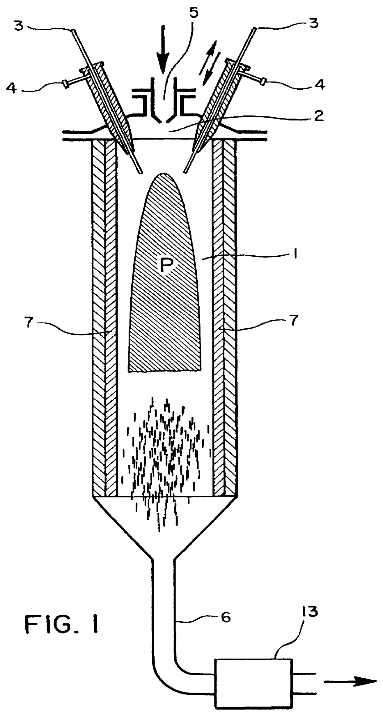
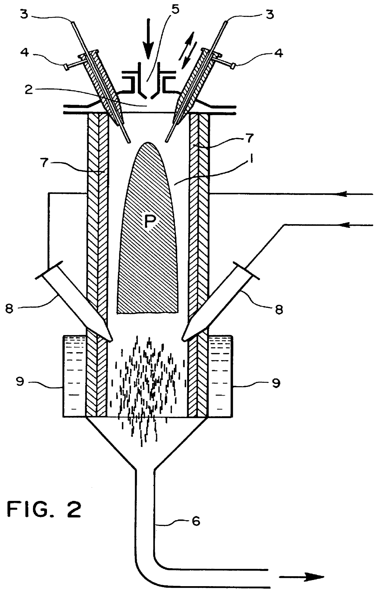
In the following examples, an apparatus essentially according to FIG. 2 is used (diameter of reaction chamber 50 cm, height of the reaction chamber 200 cm). The apparatus was controlled so that a power of 50 kW (L1) or 100 kW (L2) was available in the plasma zone. The efficiency of the system was 92% (L1) and 96% (L2).
Hydrogen was used as plasma gas.
The hydrogen formed was recycled.
Table 1 shows the method parameters for the conversions carried out.
Table 2 contains the characterization of the products obtained.
TABLE 2
Login to View More PUM
 Abstract
PCT No. PCT / EP94 / 00321 Sec. 371 Date Oct. 13, 1995 Sec. 102(e) Date Oct. 13, 1995 PCT Filed Feb. 4, 1994 PCT Pub. No. WO94 / 17908 PCT Pub. Date Aug. 18, 1994A process for converting carbon or carbonated compounds in a plasma into carbons having a defined nanostructure consists of a reaction chamber whose head part contains three electrodes, a plasma gas supply, and a carbon or carbonated compound supply. A process for preparing carbons having a defined nanostructure. Apparatus to carry out the processes.
Description
1. Field of the InventionThe invention relates to an apparatus and a method for the conversion of carbon or carbon-containing compounds in a plasma to carbons having a defined nanostructure.2. Background ArtThe production of carbon, for example soots, from carbon or carbon-containing compounds such as, for example, from hydrocarbons in a plasma is known. Thus, for example, GDR Patent Specifications 292 920, 276 098 and 211 457 relate to the production of soot by cracking hydrocarbons, for example methane, in a hydrogen plasma. The cracking is carried out in a so-called plasmatron (for figure see GDR Patent Specification 211 457) in which a hydrogen plasma jet heated to 3500 to 4000 K cracks the injected hydrocarbon. This apparatus can be described as a standard apparatus for the plasma-chemical production of soots from hydrocarbons. The apparatus mentioned and the methods associated therewith are consequently completely suitable for producing the standard carbons such as soot in a r...
Claims
Login to View More Application Information
Patent Timeline
 IPC IPC(8): B01J19/08C01B31/00C01B31/02C09C1/48C09C1/44C08J7/00
CPCB01J19/088B82Y30/00B82Y40/00C01B31/0206C01B31/0213C09C1/485C01B32/15C01B32/154C01P2002/30
InventorSCHWOB, YVANFISCHER, FRANCISFULCHERI, LAURENTWILLEMEZ, PIERRE
OwnerТІМКАЛ SА