Device for measuring the mass of a fluid element

a fluid element and measuring device technology, applied in the direction of liquid/fluent solid measurement, volume metering, instruments, etc., can solve the problems of buckling of the wire grating, disadvantageous change in the characteristic curve of the measuring element, and relatively expensive flow rectifiers with gratings of different mesh widths can be combined with one another

Inactive Publication Date: 2000-09-05
ROBERT BOSCH GMBH
View PDF8 Cites 16 Cited by
  • Summary
  • Abstract
  • Description
  • Claims
  • Application Information

AI Technical Summary

Problems solved by technology

Embedding the wire grating in the plastic results in the disadvantage that with a change in temperature and with the aging of the plastic of the flow rectifier due to creeping processes, a buckling of the wire grating can occur.
The buckling of the wire grating, though, leads to a disadvantageous change in the characteristic curve of the measuring element.
The permanent fastening of the grating to the flow rectifier results in the further disadvantage that only relatively costly flow rectifier...

Method used


Image

  • Device for measuring the mass of a fluid element
  • Device for measuring the mass of a fluid element
  • Device for measuring the mass of a fluid element

Examples


Embodiment Construction

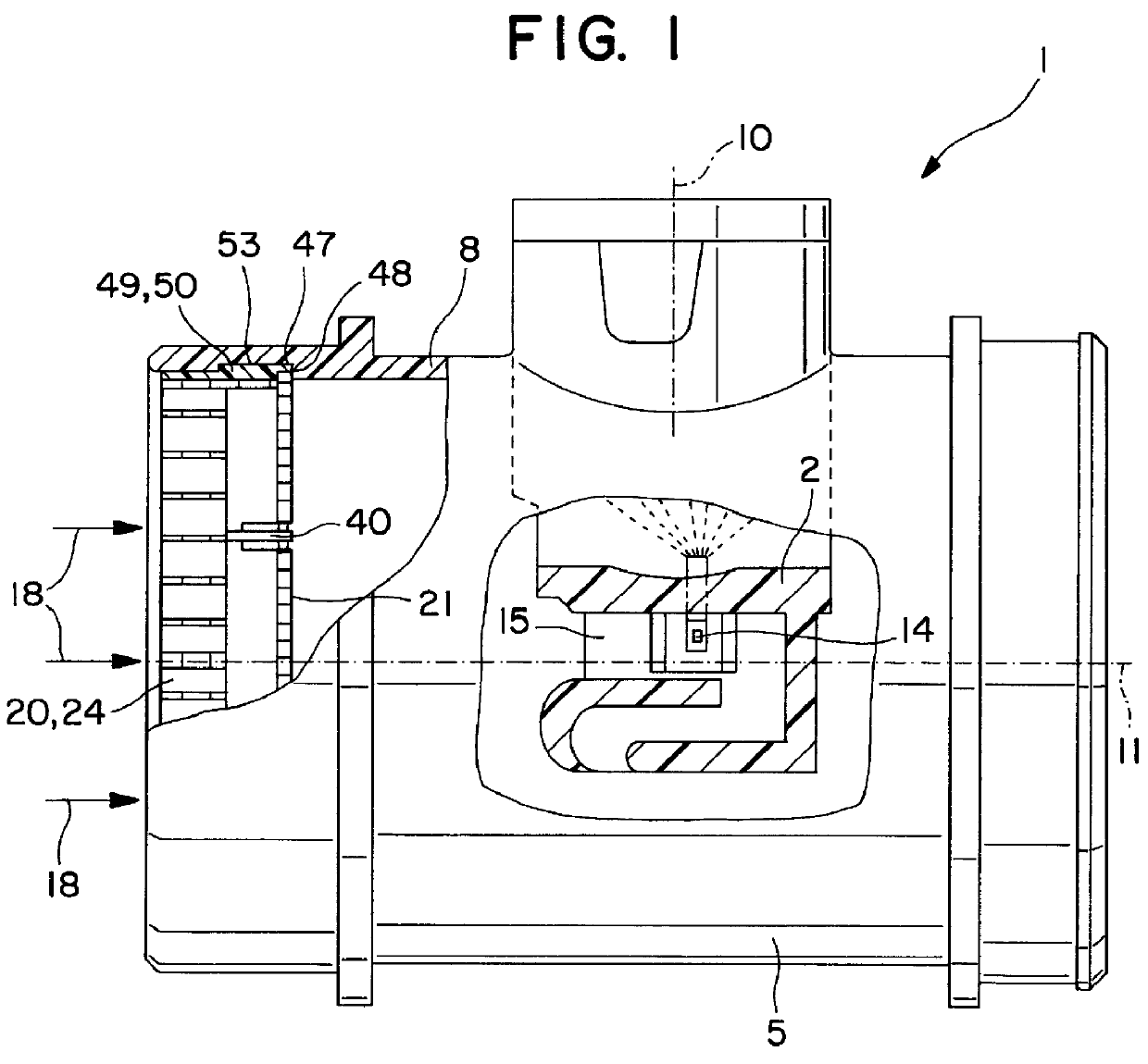
FIG. 1 shows a device 1 for measuring the mass of a flowing medium, in particular the intake air mass of internal combustion engines, in a partially sectional representation. The internal combustion engine can be a mixture compressing engine with externally supplied ignition, or can also be an air compressing, self-igniting engine. The device 1 has a measuring part 2, which is inserted, for example in plug-in fashion, into a measurement fitting 5 of the device 1. The measuring part 2 has a for example slender, rod-like, block-shaped form that extends elongated in the direction of a plug axis 10, and is inserted, for example in plug-in fashion, into an opening let into a wall 8 of the measurement fitting 5. The wall 8 defines a flow cross section that has a for example circular cross section in the center of which a central axis 11 extends in the direction 18 of the flowing medium, parallel to the wall 8 and is oriented perpendicular to the plug axis 10. The direction of the flowing ...


PUM


Abstract

PCT No. PCT/DE97/02358 Sec. 371 Date Aug. 18, 1998 Sec. 102(e) Date Aug. 18, 1998 PCT Filed Oct. 15, 1997 PCT Pub. No. WO98/27408 PCT Pub. Date Jun. 25, 1998Device for measuring the mass of a flowing medium has a measuring element accommodated in a measurement fitting, wherein a flow rectifier with a grating is provided upstream of the measuring element. For simple manufacturing, assembly, and precise alignment of a grating in relation to a flow rectifier, the flow rectifier has detent elements that can elastically deform during installation of the grating in order to secure the grating to the flow rectifier in a detachable fashion. The device provided for measuring the mass of a flowing medium, in particular for measuring the flow of an intake air mass for internal combustion engines.

Description

PRIOR ARTThe invention is based on a device for measuring the mass of a flowing medium. A device has already been disclosed (EP-PS 0 458 998), which has a measuring element accommodated in a measurement fitting, wherein a flow rectifier and a grating are accommodated upstream of the measuring element. The flow rectifier is provided to generate as uniform a flow as possible over the entire inner cross section. The grating permanently fastened to the flow rectifier is intended to produce extremely fine eddies in the flow in order to produce flow conditions that are as constant as possible downstream of the grating so that a stabilization of the measurement signal is produced at the measuring element. In order to prevent a dispersion of the characteristic curve of the measurement signal emitted by the measuring element, it is particularly important that the grating be disposed in a precise alignment to the flow rectifier. This is carried out in the known device by embedding the grating...

Claims


Application Information

Patent Timeline
IPC IPC(8): F15D1/02F15D1/00G01F1/684G01F15/00
CPCF15D1/02G01F1/6842G01F15/00G01F1/684
Inventor RILLING, HEINZ
Owner ROBERT BOSCH GMBH
Why Eureka
Try Eureka