Fluid dispensing systems

a technology of fluid dispensing system and fluid dispensing container, which is applied in the direction of gravity filters, water treatment locations, cation exchangers, etc., can solve the problems of reducing the fluid carrying capacity of the container, affecting the life of the main filter portion, and having no means by which the water may be filtered

Inactive Publication Date: 2000-09-12
CRANSHAW CHRISTOPHER JAMES
View PDF27 Cites 69 Cited by
  • Summary
  • Abstract
  • Description
  • Claims
  • Application Information

AI Technical Summary

Benefits of technology

An advantage of having such a pre-filter portion is that if the fluid to be filtered is particularly dirty, the pre-filter portion, such as a filter paper, will become dirty or clogged up, instead of the main filter portion

Problems solved by technology

However, these bottles typically have no means by which the water may be filtered before being dispensed from the bottle.
However, a disadvantage associated with the use of water purification tablets is that they leave the water with an unpleasant taste or tang.
Although this provides a system for filtering fluid before it is drunk or used by the user of the fluid storage apparatus, this apparatus suffers from a number of disadvantages.
One disadvantage is that by the provision of two fluid storage areas, the fluid carrying capacity of the container is substantially halved, and hence water that has already been filtered must be carried together with unfiltered water.
In addition, the two-step procedure of squeezing the first fluid storage area so that the water flows to the second f

Method used


Image

  • Fluid dispensing systems
  • Fluid dispensing systems
  • Fluid dispensing systems

Examples


Embodiment Construction

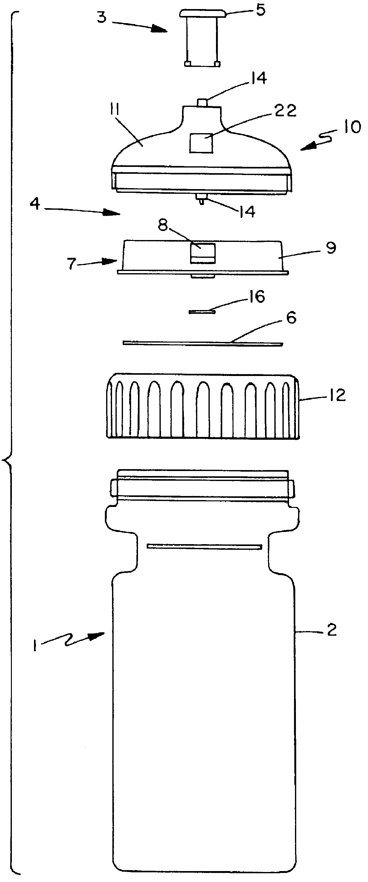
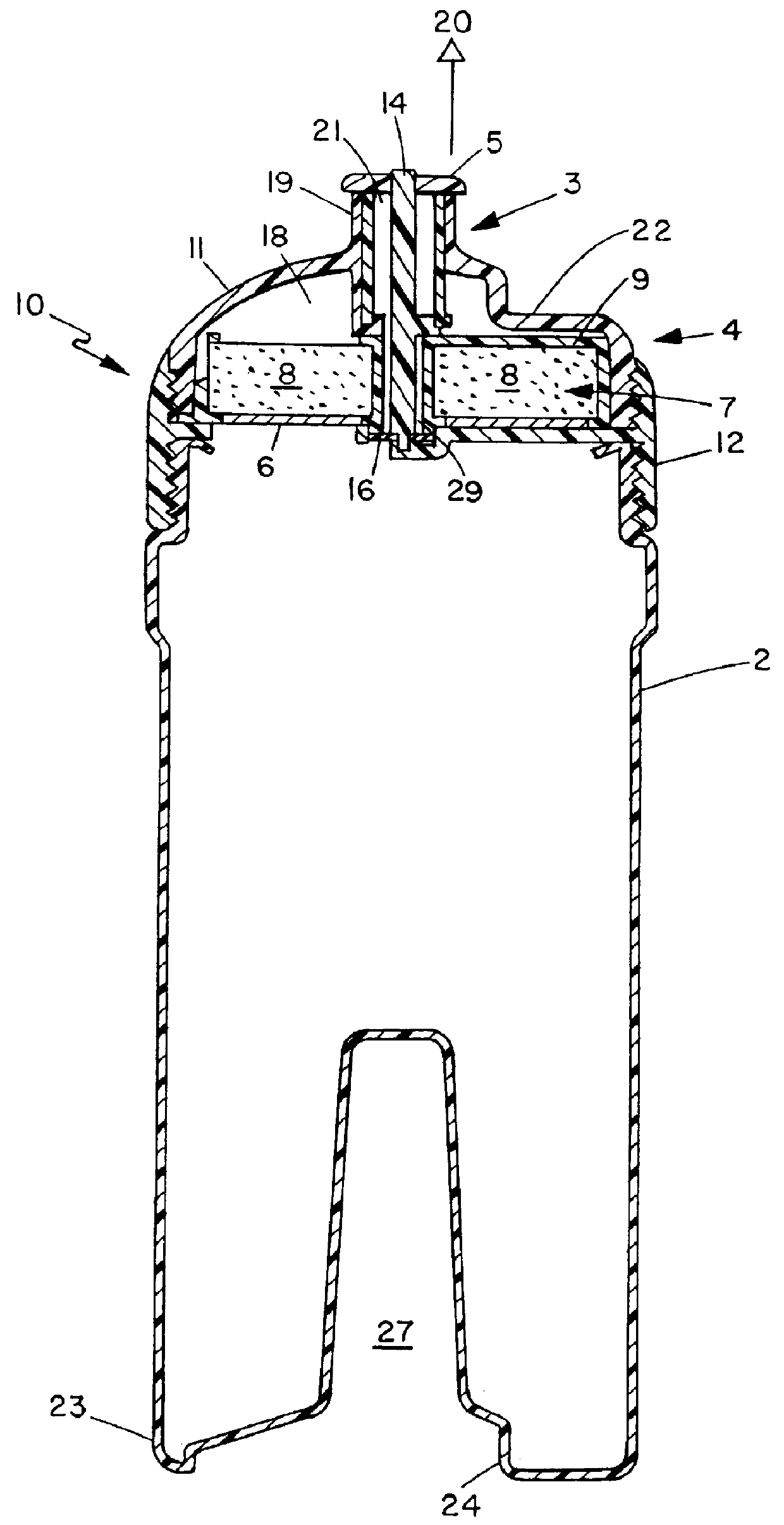
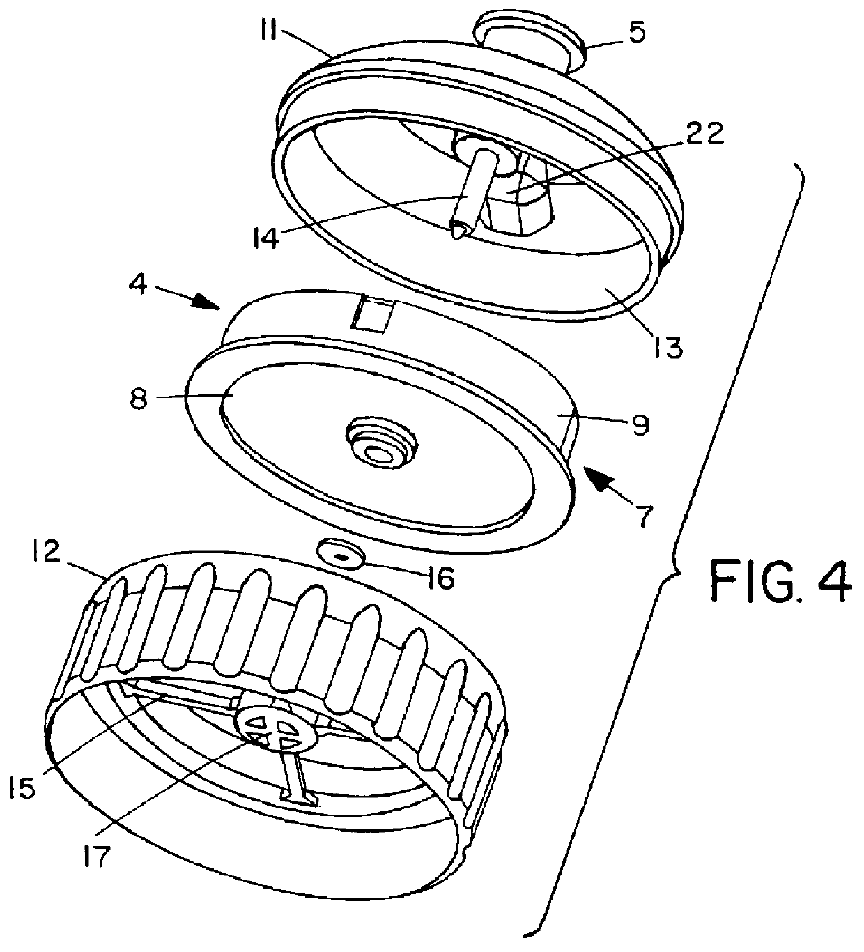
Having regard to FIGS. 1 and 2, there is shown fluid dispensing apparatus generally indicated by arrow 1. The fluid dispensing apparatus 1 comprises a fluid storage portion 2, a fluid exit portion 3, and filtering means generally indicated by arrow 4 disposed between the fluid storage portion 2 and the fluid exit portion 3.

The fluid storage portion 2 has a capacity of approximately one liter, and is comprised of a substantially flexible plastic material, similar to the plastic material utilised in presently available drink bottles for cyclists and the like. It may be appreciated therefore that the filter storage portion 2 is comprised of a substantially rigid yet flexible, material whereby the fluid storage portion 2, and hence the fluid dispensing apparatus 1 is able to be free standing.

The fluid storage portion 2 is comprised of blow-moulded polypropylene.

The fluid exit portion 3 is in the form of an adjustable cap 5. The cap 5 is in the form of presently known prior art caps util...


PUM

PropertyMeasurementUnit
Diameteraaaaaaaaaa
Flexibilityaaaaaaaaaa

Abstract

PCT No. PCT/NZ96/00052 Sec. 371 Date Dec. 31, 1997 Sec. 102(e) Date Dec. 31, 1997 PCT Filed May 30, 1996 PCT Pub. No. WO96/38382 PCT Pub. Date Dec. 5, 1996This invention relates to fluid dispensing apparatus. The fluid dispensing apparatus comprises a fluid storage portion comprised primarily of a substantially flexible material, a fluid exit portion, and a filter cartridge disposed between the fluid storage portion and the fluid exit portion. The arrangement and construction is such that the action of squeezing and/or inverting the fluid storage portion forces fluid stored withing the fluid storage portion to pass through the filter cartridge and towards or out through the fluid exit portion.

Description

This invention relates to improvements in and relating to fluid dispensing systems, and particularly with respect to fluid dispensing systems that involve filtration of the fluid before the fluid is dispensed. It is envisaged that the invention may be particularly suitable as a water bottle which allows for filtration of water within the water bottle before it is dispensed therefrom. However, it is to be understood and appreciated that the invention is not to be limited to such use.Currently there appears to exist a need for a convenient and user-friendly fluid dispensing apparatus which is capable of storing fluid in a fluid storage area, and then providing a means for the fluid to be filtered before it is dispensed from the apparatus.Such an apparatus may be particularly useful for people such as trampers, dwellers in crowded and / or unhygienic cities, or others, who require fluid such as water to be filtered (primarily for health reasons) prior to drinking the fluid (or using the ...

Claims


Application Information

Patent Timeline
IPC IPC(8): A47J31/60A47J31/44C02F1/00
CPCA47J31/605C02F1/003C02F2307/02
Inventor CRANSHAW, CHRISTOPHER JAMES
Owner CRANSHAW CHRISTOPHER JAMES
Why Eureka
Try Eureka