Circuits for controlling reciprocation amplitude of a linear motor

a linear motor and reciprocating amplitude technology, applied in the direction of motor/generator/converter stopper, dynamo-electric converter control, propulsion system, etc., can solve the problem of increasing the cost of a pwm motor driver by its requirement for electronic switches capable of high, source of serious electromagnetic interference (emi), and increasing the cost of a pwm motor driver. problem, to achieve the effect of high efficiency

Inactive Publication Date: 2000-09-12
REDLICH ROBERT WALTER
View PDF3 Cites 19 Cited by
  • Summary
  • Abstract
  • Description
  • Claims
  • Application Information

AI Technical Summary

Benefits of technology

The invention uses an H-bridge to apply to a linear motor a train of controllably variable duration pulses whose repetition frequency is equal to the motor oscillation frequency and whose polarity alternates from positive to negative. Between pulses, all of the active elements of the H-bridge are turned off. Compared to PWM of prior art, the number of switching events per unit time in the present invention is lower by a typical factor of 250, which as two consequences that permit the achievement of the objects of the invention. First, switching can be slow, since, even though the loss per switching event is then high, the rate of switching is so low that switching loss per unit time will be lower by a typical factor of 10 than that of a PWM system, even if bipolar transistors (typical switching time about 20 times greater than a FET) are used as switching elements in the invention. Second, low switching rate and high switching time both act to reduce EMI generated by the invention to practical insignificance.
The invention may use a complementary H-Bridge, in which the high and low side switching elements in the case of a FET bridge are P-channel FETs and N channel FETs respectively, and, in a bipolar transistor bridge, PNP and NPN transistors respectively. This arrangement offers simplicity and economy since all switching signals swing between the same power supply rails. Switching logic is simple, and expensive high side drivers needed by a non-complementary H bridge are obviated.
FIG. 7 shows a preferred embodiment of a non-complementary H-bridge which uses all N-channel field effect transistors, and high side drivers to achieve the goals of the invention with high efficiency.

Problems solved by technology

A disadvantage of a PWM motor drive is that it can be a source of serious electromagnetic interference (EMI) unless it is provided with costly shielding and filtering.
Since devices equipped with DC powered linear motors may be used near radios or TV sets, very effective EMI suppression is essential to such devices and adds significant cost.
The cost of a PWM motor driver is increased by its requirement for electronic switches capable of high speed switching, which are needed if switching losses are to be acceptably low.
Field effect transistors (FETs) are usually used, but are relatively expensive compared to bipolar transistors, which are generally inapplicable to PWM because their relatively slow switching would cause excessive switching loss.

Method used


Image

  • Circuits for controlling reciprocation amplitude of a linear motor
  • Circuits for controlling reciprocation amplitude of a linear motor
  • Circuits for controlling reciprocation amplitude of a linear motor

Examples


Embodiment Construction

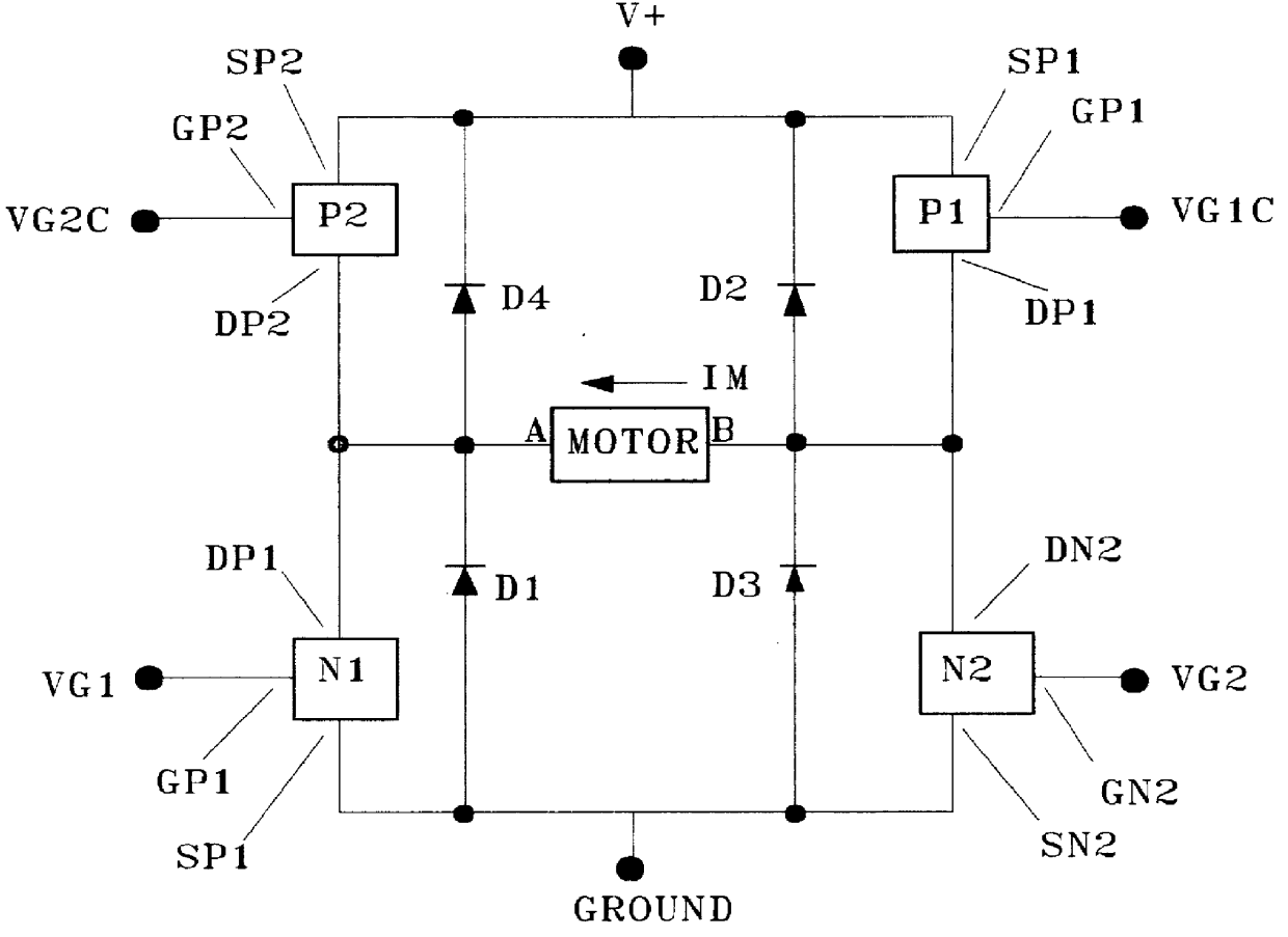
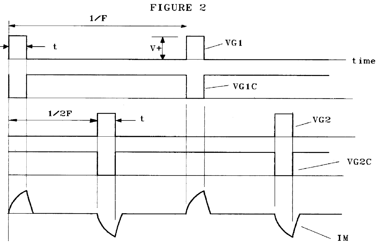
Referring to FIGS. 1 and 2, N1 and N2 are N channel FETs, P1 and P2 are P channel FETs. SN1, GN1, DN1 are respectively the source, gate and drain terminals of N1; with analogous notation identifying the source, gate, and drain terminals of N2, P1, and P2, V+ to ground is a DC voltage obtained from a source such as a battery or solar panel. The gate signals applied to GN1, GN2, GP1 and GP2 are VG1, VG2, VG1C, and VG2C respectively. VG1C is the complement of VG1 and VG2C is the complement of VG2. All gate signals swing between V+ and ground, and all repeat at frequency F, where F is the required frequency of motor oscillation. VG2 is displaced in time from VG1 by (1 / (2 F)), but has the same pulse duration (t) as VG1.

Since a P channel FET turns on when its gate is negative relative to its source, and an N channel FET turns on when its gate is positive relative to its source, the switching elements are turned on and off in diagonal pairs, in the sequence:

a) N1 and P1 on, N2 and P2 off.

b...


PUM


Abstract

Circuits for converting DC voltage into controllably variable amplitude AC voltage, for the purpose of driving an oscillating linear motor with controllable amplitude, are disclosed. Unlike pulse width modulation circuits for the same purpose, the disclosed circuits do not require suppression of electromagnetic interference and have negligible switching loss.

Description

This invention relates to an electronic circuit for generating controllably variable alternating voltage used to energize a linear motion electric motor, for the purpose of causing the motor's moving element to oscillate with controllably variable amplitude.In practice, the function of a linear motion electric motor, for example the motor disclosed in U.S. Pat. No. 4,602,174, is to drive a mechanical element such as the piston of a compressor with controllably variable amplitude oscillatory motion. To accomplish this, the amplitude of the voltage applied to the motor winding must be controllably variable.If the source of electrical power for the linear motor is constant voltage AC such as 120 VRMS, 60 hz., controllably variable voltage to energize the motor can be generated inexpensively with a triac, using, for example, the circuit disclosed in U.S. Pat. No. 5,592,073.If the source of electrical power for the linear motor is DC, e.g. a battery or solar panel, voltage from the sourc...

Claims


Application Information

Patent Timeline
Patent Type & Authority Patents(United States)
IPC IPC(8): H02P25/02
CPCH02P25/027H02P25/032
Inventor REDLICH, ROBERT WALTER
Owner REDLICH ROBERT WALTER
Why Eureka
Try Eureka