Linearized switch-based power amplifier

a power amplifier and switch technology, applied in the field of linearization techniques of power amplifiers, can solve the problems of additional interference in the channel or in the other channel, interference in these and other channels, and signal energy leakage to undesired channels, so as to reduce the distortion, the switch speed is faster, and the non-linearity is more.

Inactive Publication Date: 2007-12-18
TELEFON AB LM ERICSSON (PUBL)
View PDF12 Cites 8 Cited by
  • Summary
  • Abstract
  • Description
  • Claims
  • Application Information

AI Technical Summary

Benefits of technology

[0018]A particular advantage is that it is possible to allow more non-linearity in the switch stage, since the negative feedback enables suppression of the distortion caused by non-linearities in the switches. Thus, somewhat slower switches can be used, which means that less expensive switch technologies are available.
[0019]Another related aspect of the technology concerns an implementation using a digital modulator. In such a case, the feedback signal has to be digitized in an A / D-converter. In order to handle the very short-time, high signal-level glitches caused by non-ideal switching, a wide-band filter is introduced before the A / D-converter in the feedback path for averaging the switching glitches and thus reducing the required sampling frequency and the required dynamic range of the A / D-converter. By using a wide-band filter, a minimum of delay is introduced into the feedback path and hence the stability of the overall system is maintained.

Problems solved by technology

If the linearity is inadequate, the simultaneously amplified channels cross-modulate, causing interference in these and other channels.
The non-linearities manifest themselves as cross-modulation of different components of the signal, leading to leakage of signal energy to undesired channels.
In addition, the spectra of the signal components are normally broadened, causing additional interference within the channels or in other channels.
In the case of multi-level linear modulation such as QAM (Quadrature Amplitude Modulation), the non-linearities will normally lead to distortion of the constellation diagram.
An additional complication is that the signals often have wide bandwidth, or wide combined bandwidth, which means that the fluctuations between high and low amplitude levels are fast.

Method used


Image

  • Linearized switch-based power amplifier
  • Linearized switch-based power amplifier
  • Linearized switch-based power amplifier

Examples


Embodiment Construction

[0035]Power amplifiers can be found in various applications in many fields of technology such as consumer electronics, radar technology and radio communication. In the following, the invention will be described with reference to a particular application within the field of radio communication. It should though be understood that the invention is not limited thereto, and that other applications are feasible as well.

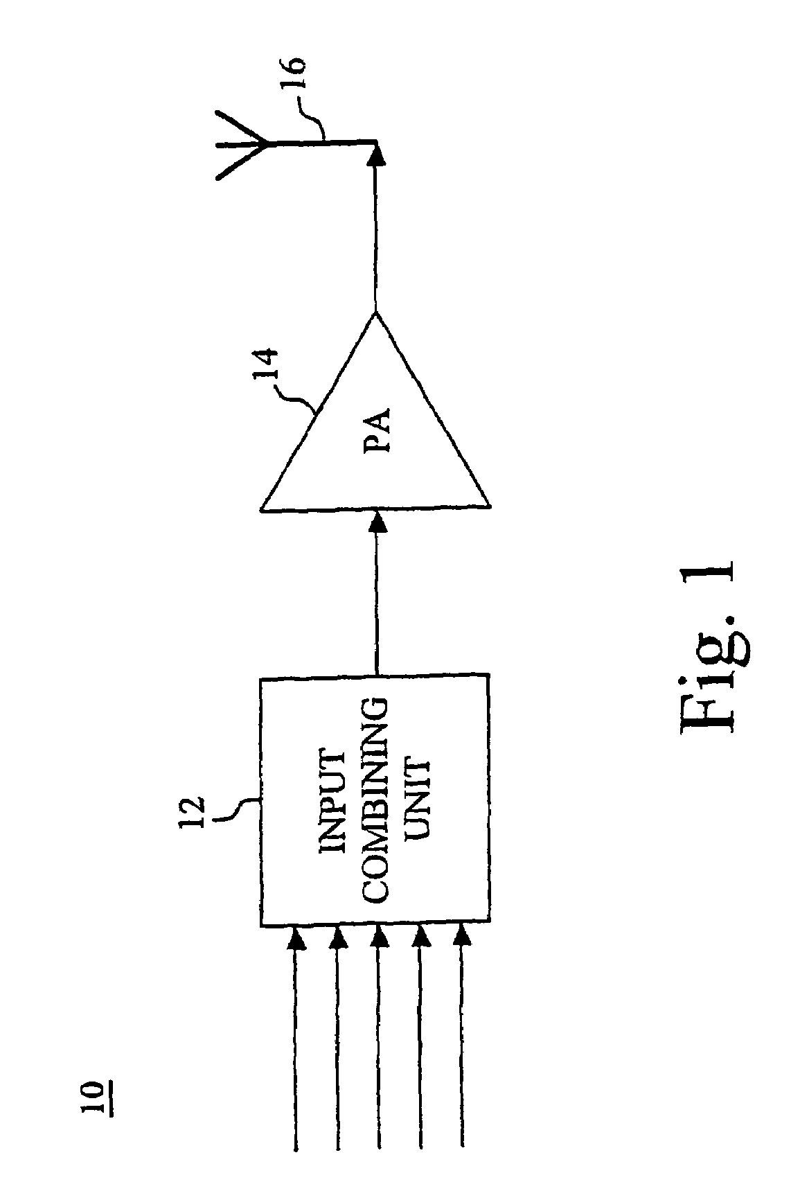
[0036]In a typical radio application, as schematically illustrated in the high-level block diagram of FIG. 1, a power amplifier is arranged in a radio transmitter for simultaneous amplification of several narrow-band channels. In a very basic realization, the transmitter 10 comprises a general input unit 12 for combining the input signals into a complex multi-channel signal, a power amplifier 14 for simultaneous amplification of the multiple channels and a transmission element 16. Such a basic realization of course requires that the input signals are modulated RF signals w...


PUM


Abstract

A power amplifier comprises a level-discretization modulator (210) and a mixing and amplifying stage (225), in combination with a properly designed negative feedback path. The feedback path forms an error compensation loop together with a properly selected forward path. The forward path includes at least the mixing and amplifying stage (225), which provides frequency up-conversion to the radio frequency band and switch-based amplification. The negative feedback path includes a down-conversion mixer (280) for down-conversion to the initial frequency band, and compensates for distortion caused by components of the forward path.

Description

[0001]This application is the U.S. national phase of international application PCT / SE02 / 00809, filed Apr. 25, 2002, which designated the U.S.TECHNICAL FIELD OF THE INVENTION[0002]The present invention generally relates to the field of power amplifiers, and more particularly to linearization techniques for power amplifiers.BACKGROUND OF THE INVENTION[0003]In cellular base stations, satellite communication systems as well as other communication and broadcasting systems of today, it is often desirable to amplify multiple radio frequency (RF) channels simultaneously in the same power amplifier instead of using a dedicated power amplifier for each channel. However, when using one and the same power amplifier for the simultaneous amplification of multiple FDMA / TDMA (Frequency Division Multiple Access / Time Division Multiple Access) or CDMA (Code Division Multiple Access) channels or when using multi-level linear modulation formats, a high degree of linearity is required so that the phases ...

Claims


Application Information

Patent Timeline
Patent Type & Authority Patents(United States)
IPC IPC(8): H04K1/02H03F3/217H04B1/04
CPCH03F3/2175H03F3/2178H04B2001/0433H03F2200/331H03F1/34H03F3/24
Inventor FONDEN, TONYHELLBERG, RICHARD
Owner TELEFON AB LM ERICSSON (PUBL)
Why Eureka
Try Eureka