Apparatus and method for automatic mode selection in a communications receiver

Inactive Publication Date: 2000-09-12
HANGER SOLUTIONS LLC
View PDF11 Cites 42 Cited by
  • Summary
  • Abstract
  • Description
  • Claims
  • Application Information

AI Technical Summary

Problems solved by technology

However, as the bandwidth response is increased to accommodate high speed performance, the amount of background noise integrated into the receiver response also increases due to the wider bandwidth spectrum.
However, because the detection threshold is higher for high speed mode, low speed signal transitions may be lost.
The link failure may be due to a limitation in the light interface, such as high ambient light levels, or

Method used


Image

  • Apparatus and method for automatic mode selection in a communications receiver
  • Apparatus and method for automatic mode selection in a communications receiver
  • Apparatus and method for automatic mode selection in a communications receiver

Examples


Embodiment Construction

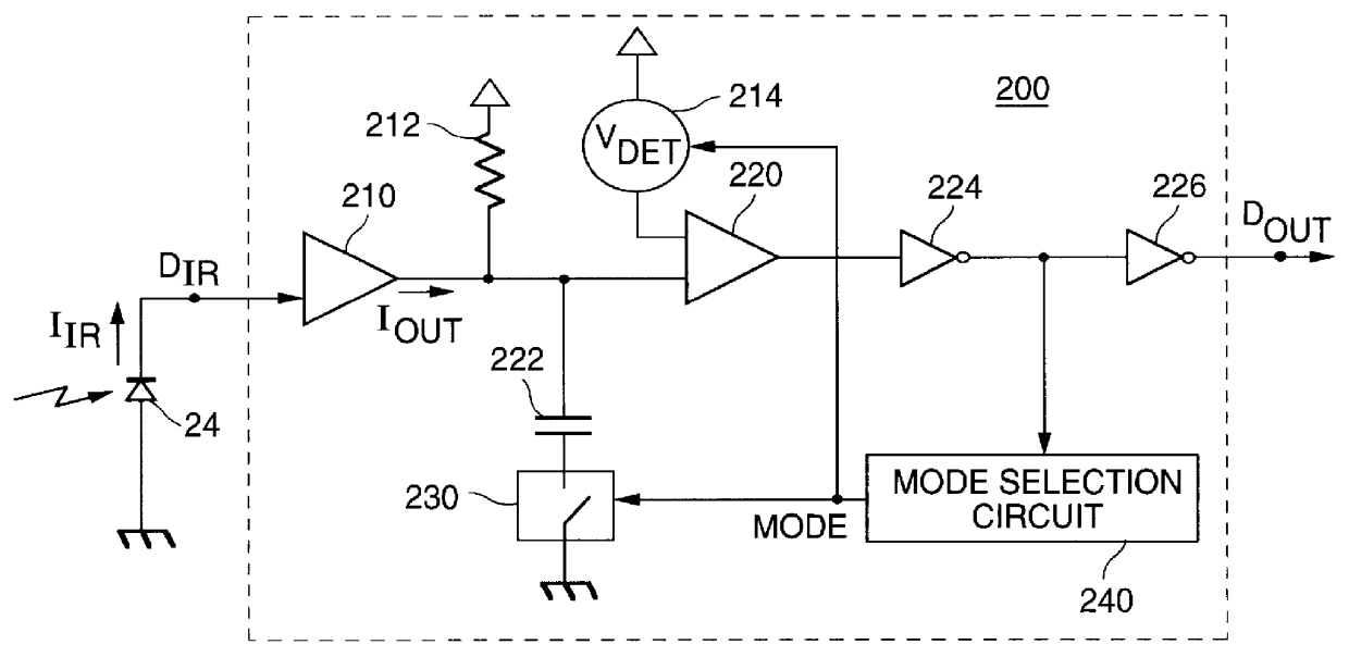
An embodiment of an infrared receiver 200 according to the present invention is shown in FIG. 2. A transconductance amplifier 210 converts the current signal I.sub.IR received from the photo-diode 24 at input terminal D.sub.IR to an output current signal I.sub.OUT. I.sub.OUT is converted to a voltage signal by resistor 212 and then compared to a detect threshold voltage V.sub.DET, generated by variable voltage reference 214, by comparator 220. Comparator 220 outputs a demodulated data signal waveform that is inverted by inverter 224. The inverted data signal output by inverter 224 is input to inverter 226 for output of a recovered data signal at output terminal D.sub.OUT.

The inverted data signal output from inverter 224 is also input to mode selection circuit 240. Mode selection circuit 240 monitors the transitions in the inverted data signal stream and outputs a mode selection signal which controls the selection of the detection threshold voltage V.sub.DET in variable voltage refer...


PUM


Abstract

A method and apparatus are shown for automatically adjusting a response bandwidth and input sensitivity of a communications receiver responsive to a frequency of a received data signal. The response bandwidth is adjusted by switching a low pass filter into a receive path of the receiver when the received data signal is a low speed data signal and switching the low pass filter out of the receive path when the received data signal is a high speed data signal. The input sensitivity is adjusted by either changing a detection threshold of a comparator in the receive path or varying a gain of an input amplifier in the receive path. The high speed data signal is discerned when the low pass filter limits the response bandwidth of the receiver by a mode selection circuit which examines the duration of multiple pulses in a pulse train in the received data signal.

Description

1. Field of InventionThe present invention relates to a circuit and method for automatically selecting between a high speed operating mode and a low speed operating mode in a communications receiver responsive to the mode of the incoming transmission signal.2. Description of the Related ArtInfrared wireless data communication is a useful method for short range (in the approximate range of 0-10 meters) wireless transfer of data between electronic equipment; such as, cellular phones, computers, computer peripherals (printers, modems, keyboards, cursor control devices, etc.), electronic keys, electronic ID devices, and network equipment. Infrared wireless communication devices typically have the advantages of smaller size, lower cost, fewer regulatory requirements, and a well defined transmission coverage area as compared to radio frequency wireless technology (i.e. the zone of transmission is bounded by physical walls and therefore more useful in an office environment). In addition, i...

Claims


Application Information

Patent Timeline
IPC IPC(8): H04L25/02H04L25/06
CPCH04L25/0262H04L25/062H03F3/087
Inventor NORTH, BRIAN B.
Owner HANGER SOLUTIONS LLC
Why Eureka
Try Eureka