Anti-jamming array antenna

a type of antenna and array technology, applied in the direction of individual energised antenna arrays, direction finders using radio waves, instruments, etc., can solve the problems of high signal-to-noise ratio, excessive number of radiating elements, and difficulty in meeting the fineness of angular resolution,

Inactive Publication Date: 2000-09-26
THOMSON CSF SA
View PDF9 Cites 34 Cited by
  • Summary
  • Abstract
  • Description
  • Claims
  • Application Information

AI Technical Summary

Problems solved by technology

In practice, the requirement of fineness of angular resolution is more difficult to meet than that of a high signal-to-noise ratio.
Hence, if no compromise is accepted, the end result is an excessive number of radiating elements.
However, it has the disadvantage of not being usable at transmission, requiring costly equipment for the digitization of the signals of the radiating elements and requiring a very large number of computation operations.
This leads to the appearance of array and / or scattered lobes so that the reduced beam-forming leads to poor performance characteristics of the antenna on a wide angular field.
This drawback may be circumvented by a Doppler filtering upline with respect to the grouping of the two reception signals resulting from the reduced computational beam-forming operations, but this means that it is necessary to double the Doppler filtering equipment.

Method used


Image

  • Anti-jamming array antenna
  • Anti-jamming array antenna
  • Anti-jamming array antenna

Examples


Embodiment Construction

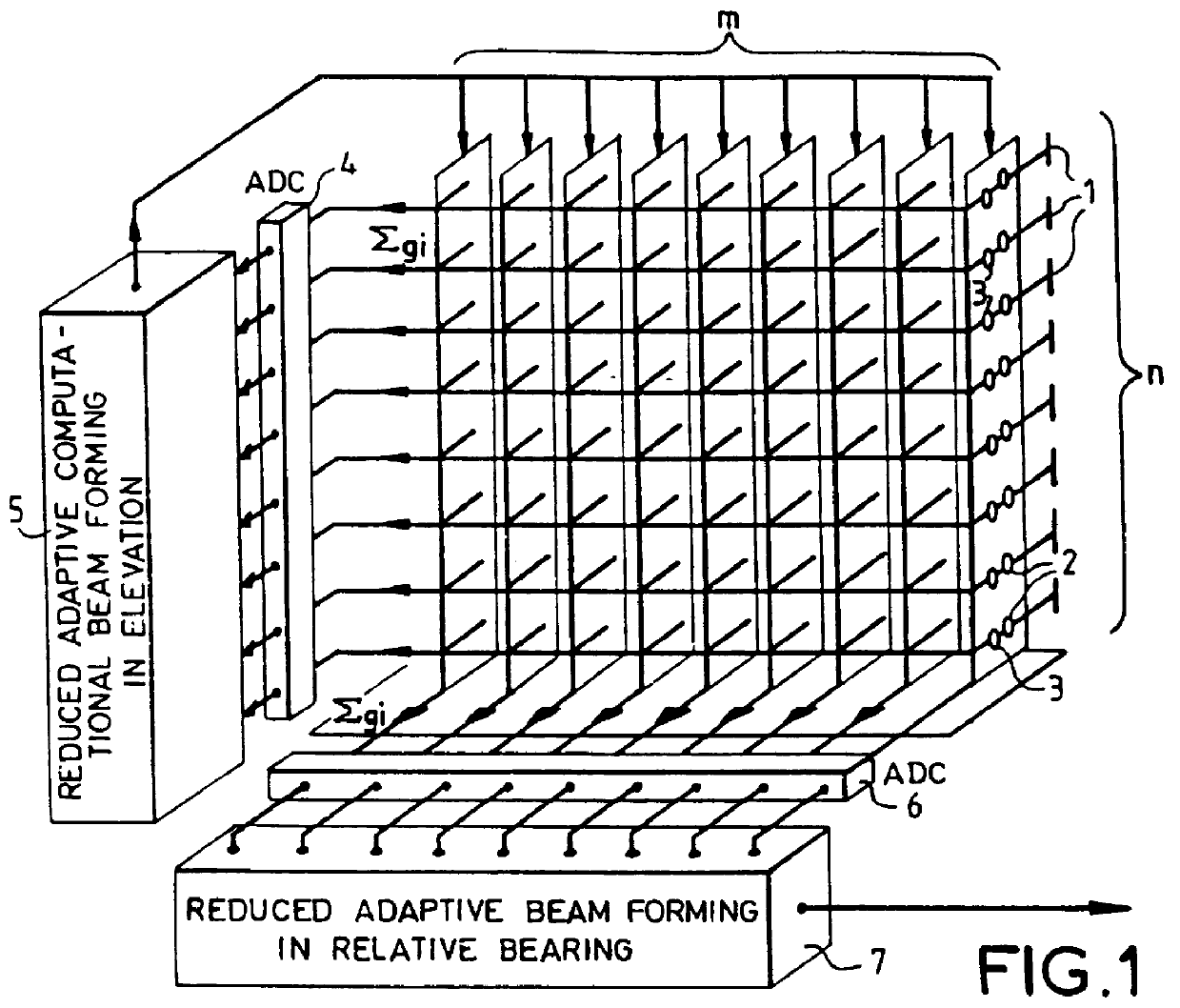
FIG. 1 shows a flat array antenna bringing together a number of radiating elements 1 uniformly distributed on m columns and n rows in a mesh of about .lambda. / 2 (.lambda. being the wavelength of use of the antenna) to meet the surface sampling criterion that ensures the absence of array lobes in the case of wide angle electronic scanning. Each radiating element 1 is individually fitted out with a controlled phase-shifter module 2 complemented by a controlled attenuator module 3.

It is possible, with a view to simplifying the configuration of the antenna, to have several radiating elements of the antenna served by one and the same controlled module 2.

The controlled modules 2 and 3 are controlled primarily by the antenna aiming circuit (not shown) which brings about the orientation, both at transmission and at reception, of the wave plane of the antenna in the desired direction in relative bearing and in elevation, in bringing into play essentially the phases and, on an accessory basis...


PUM


Abstract

This array antenna with anti-jamming in reception for radioelectrical or ultrasound waves is provided with radiating elements fitted out individually or in groups with amplitude-controlled and phase-controlled passive or active modules enabling aiming at transmission as well as at reception by analog beam-forming. It possesses a reception anti-jamming circuit carrying out successively two reduced, adaptive computational beam-forming operations, one in elevation which is performed on a grouping, in horizontal alignments, of the reception signals of the radiating elements and working on the reception signals by modifying the settings of the controlled modules and the other in relative bearing, performed on a grouping, in vertical alignments, of the signals of the radiating elements that which it phase-shifts and adds up to form a reception channel for the total antenna. The reception anti-jamming thus obtained has performance characteristics comparable to those that would result from a full adaptive beam-forming operation. At the same time, it requires a far smaller volume of processing.

Description

1. Field of the InventionThe present invention relates to an array type antenna for radioelectrical or ultrasound waves, protected against jamming in reception. This antenna has radiating elements or groups of radiating elements individually fitted out with active or passive amplitude-controlled and phase-controlled modules enabling an aiming operation, at both transmission and reception, by analog beam-forming, and adaptive computational beam-forming means carrying out reception anti-jamming.2. Description of the Prior ArtHereinafter, amplitude-controlled and phase-controlled active or passive modules shall be simply called controlled modules, purely with a view to simplification.An array antenna consists of an assembly of radiating elements distributed in an array, most usually a surface array, with a mesh size of about .lambda. / 2 , i.e. half of the wavelength of the radiation transmitted or received, to prevent the appearance of array lobes that disturb the directivity of the ant...

Claims


Application Information

Patent Timeline
Patent Type & Authority Patents(United States)
IPC IPC(8): G01S7/36H01Q3/26H01Q21/22G01S7/28
CPCG01S7/36H01Q3/2617H01Q21/22H04K3/228G01S7/2813H04K2203/32
Inventor CHAMPEAU, ANDRE
Owner THOMSON CSF SA
Why Eureka
Try Eureka