Drum brake device

a technology of drum brake and drum pedal, which is applied in the direction of mechanically actuated drum brake, fluid actuated drum brake, mechanical apparatus, etc., can solve the problems of increasing pedal stroke, repulsion of brake pedal, disconcerting the driver, etc., and achieves the effect of reducing the strength of the periphery and removing any discomfort or anxiety for the driver

Inactive Publication Date: 2000-10-03
NISSHINBO IND INC
View PDF15 Cites 16 Cited by
  • Summary
  • Abstract
  • Description
  • Claims
  • Application Information

AI Technical Summary

Benefits of technology

To that end, it is the first object to provide a drum brake device in which by regulating the long link to turn in one direction with respect to the brake shoes, its engaging point with the shoe clearance adjustment device can be easily observed by a temporary assembly of the link and the brake shoe.
The second object is to provide a drum brake device in which the brake shoes do not separate from the anchor block, even when the parking brake is applied, in which case no noise is generated even when a torque is generated on the brake drum, thus eliminating any discomfort or anxiety for the driver.
The third object is to provide a drum brake device in which no impact load is applied to the anchor block, hence the strength of its periphery can be reduced to make the device lighter.
The fourth object is to provide a drum brake device in which an adjustment spring and other components that affect the automatic shoe clearance adjustment device move in tandem with the brake shoes, thereby enduring a constant clearance between the brake drum and the brake shoes, even as the linings wear out.
The fifth object is to provide a drum brake device which avoid the wheel being locked because of the brake shoe biting the brake drum or usual dragging occurring between the brake lining and the brake drum.

Problems solved by technology

That is, the brake pedal is repelled which is not only disconcerting to the driver, but the pedal stroke increases in the next brake pedal application.
When the idler lever k is pivoted to rotate on the other brake shoe c, it is very difficult to check the proper alignment of the components.
The noise so generated is disconcerting to the driver.
Additionally, this impact load applied repeatedly on the anchor block can diminish the structural strength of the components.
Accordingly, the idler lever could vibrate creating a strange noise when the vehicle is in motion or the service brake is applied.
Again, this noise can be disconcerting to the driver.
This changes the energizing force of the adjustment spring energizing the adjustment lever, which has a negative effect on the automatic adjustment process when only a very minimal adjustment is required.
Moreover, in the conventional drum brake device, there are chances that the brake shoe bites the brake drum causing unusual dragging between the brake lining and the brake drum.
As a result, the wheels may be locked creating a dangerous situation to the driver.

Method used


Image

  • Drum brake device
  • Drum brake device
  • Drum brake device

Examples


first embodiment

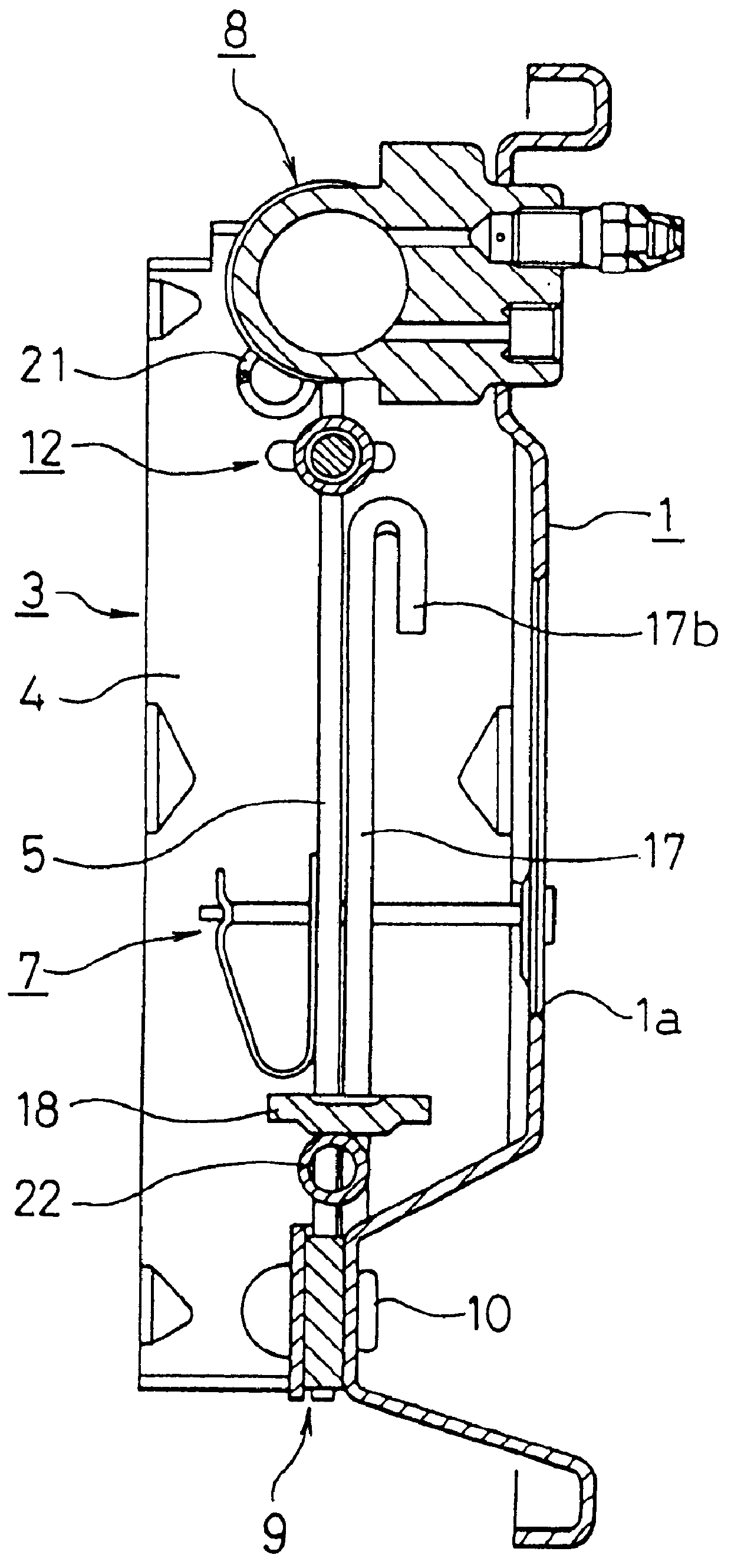
The overall configuration of the first embodiment is shown in FIGS. 1-6.

The central hole la of the back plate 1 is freely inlaid in the vehicle axle, and the back plate is affixed to a stationary part of the vehicle by four bolts inserted through the bolt holes 1b. A pair of brake shoes 2, 3, are provided to face oppositely to each other. Each shoe comprises a shoe rim 4, a shoe web 5 joined to the rim 4 to form a "T" in cross section, and lining 6 affixed around the perimeter of the shoe rim 4. Friction created s the linings are forced against the brake drum (not shown in the diagram) produces the braking action. The brake shoes 2, 3 are each mounted on top of the back plate 1 by a shoe-hold mechanism 7, 7 each comprised of a known plate spring and pin.

A service brake actuator 8, activated when the service brakes are applied, is provided between one pair of adjacent ends 2a, 3a of the pair of oppositely-facing brake shoes 2, 3, and is affixed to the back plate 1 with bolts or other...

example 2

FIG. 7 illustrates Example 2, another embodiment of this invention, in which the shoe return springs have been modified. Otherwise, all other components are virtually the same as in Example 1, and are identified with the same symbol wherein an explanation is omitted here.

That is, the two return springs 21, 22 as shown in FIG. 1 are replaced with one shoe return spring 23, a fairly thick wire spring configured in the shape of a slightly obtuse U. The middle segment of the wire spring 23 is mounted on top of the anchor block 9, and the two free ends 23a, 23a are bent so as to latch in the holes 5c, 5c bored on the anchor block side in the two brake shoes 2, 3. The wire spring 23 should be stretched in a location such that when the parking brake is applied, the one ends 2a, 3a of the brake shoes 2, 3 will open.

The configuration of the shoe return spring is not limited to that shown in Example 1 or Example 2. A variety of shapes and configurations can be used, such as splitting the seco...

example 3

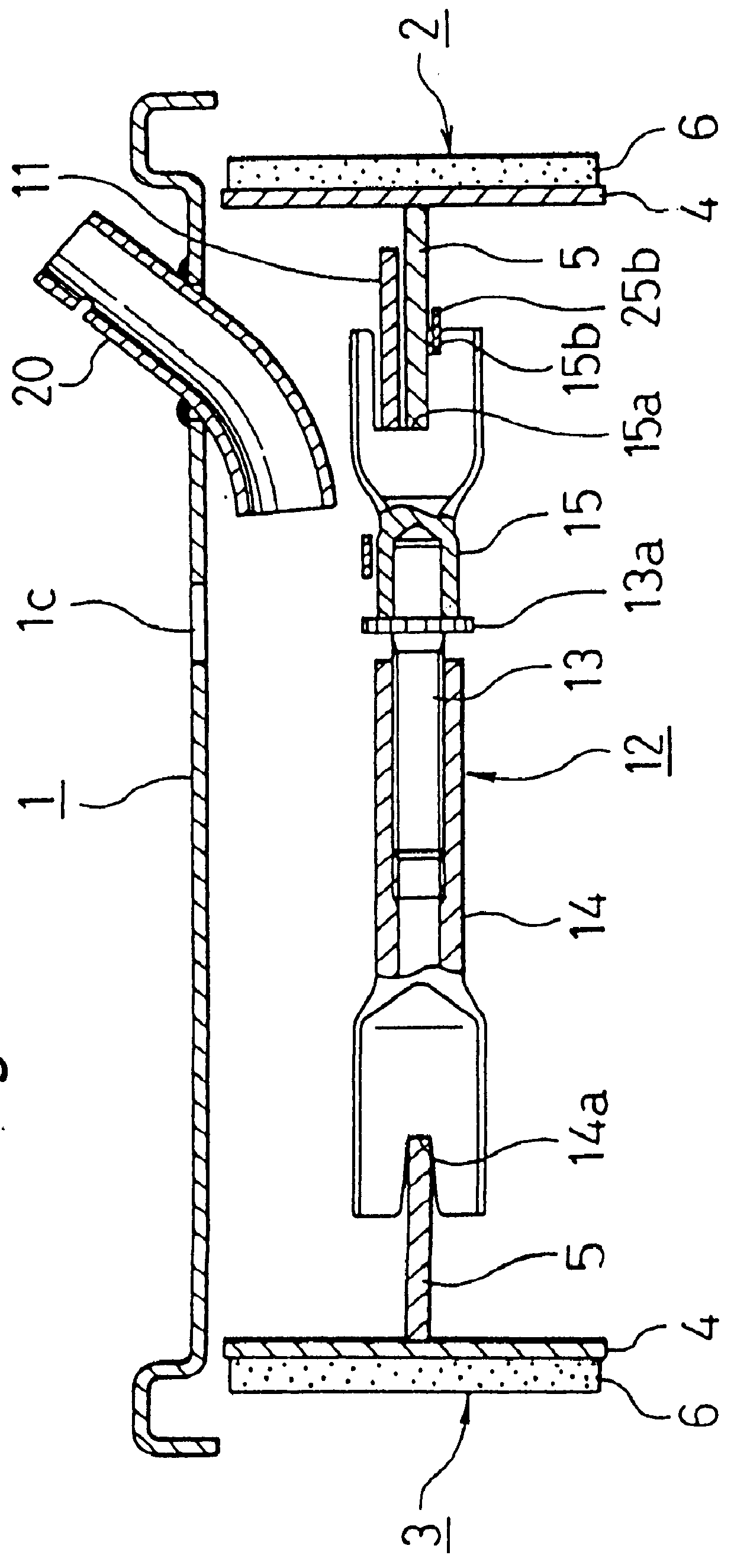
Example 3 is another embodiment of this invention shown in FIG. 1, 3, and 8 which is equipped with an incremental type of automatic shoe clearance adjustment device which is activated when the service brake is applied.

A pin 24 affixed on the one end side of the long link 11 freely penetrates through a slot 5d bored in the shoe web 5 of one brake shoe 2 and a hole 25a, provided in the middle of the adjustment lever 25. The adjustment lever 25 is pivotable around the stem component 24a which protrudes above the hole 5d. One arm 25b of the adjustment lever 25 abuts against the stepped face 15b of the notched groove 15a of the socket 15, while the other arm 25c is engages the toothed adjustment wheel 13a of the adjustment bolt 13.

Alternatively, the pin 24 can be affixed to the shoe web 5, and the adjustment lever 25 can pivot on the stem component 24a of the pin 24.

An adjustment spring 26 is stretched between another arm 25d of the adjustment lever 25 and the shoe web 5. As shown in FIG...


PUM


Abstract

A drum brake device that functions as a leading-trailing (LT) type when the service brake is applied, and as a duo-servo (DS) type when the parking brake is applied, in which the automatic shoe clearance adjustment mechanism functions precisely for a prolonged period, thereby generating no strange noise. This mechanism also eliminate any impact load applied to any of the components, thus enabling a lighter device. The middle segment of a long link 11 is pivotable in the middle of the one brake shoe 2.

Description

This invention relates to a drum brake device; more specifically, it relates to a drum brake device that functions as a leading-trailing (LT) type when the service brake is applied, and as a duo-servo (DS) type when the parking brake is applied.This type of drum brake device has been disclosed in Australian patent number AU-B1-53 491 / 79 and U.S. Pat. No. 5,275,260. The basic brake functions are the same in both devices, and the structure will be explained with reference to FIG. 15. A pair of brake shoes b, c are provided on top of a back plate a. An anchor block d is provided between the one adjacent ends of each brake shoe, and a hydraulic cylinder g is provided between the other adjacent ends of each brake shoe. A parking lever j is pivoted on one end i of one brake shoe b, and an idler lever k is pivoted so as to swing on the other brake shoe c. The first and second rods l, m are provided between the two brake shoes b, c, wherein one end n of the first rod l engages with the park...

Claims


Application Information

Patent Timeline
Patent Type & Authority Patents(United States)
IPC IPC(8): F16D65/14F16D65/56F16D65/58F16D65/38F16D51/24F16D51/00F16D51/48F16D51/50F16D65/09
CPCF16D51/24F16D51/48F16D65/58F16D65/563F16D2125/64F16D2125/60F16D51/22F16D51/50
Inventor ASAI, SEIJIKOBAY, YASUSHI
Owner NISSHINBO IND INC
Why Eureka
Try Eureka