Catalytic reactor charging system and method for operation thereof

Inactive Publication Date: 2000-10-17
COMARDO MATHIS P
View PDF9 Cites 58 Cited by
  • Summary
  • Abstract
  • Description
  • Claims
  • Application Information

AI Technical Summary

Problems solved by technology

It is well known that each worker of a charging crew will typically pour catalyst pellets at a slightly different rate so that the result can often be poor drop time uniformity thus resulting in uneven tube outages.
In some cases the catalyst pellets will bridge within some of the reaction tubes due to non-uniform drop time and catalyst compaction, thus resulting in voids that cause "hot spots" and uneven fluid pressures and temperatures within the various tubes of the reactor.
The resulting chemical product from reactors that have not been uniformly charged with catalyst is often less than optimum quality.
This type of controlled filling achieves virtually the same catalyst bed height in each of the reactor tubes but it does not take into consideration the problem of catalyst pellet bridging and compaction respective reaction tubes.
Thus, though the upper end of the catalyst beds in the tubes can be virtually the same, voids within part of the reaction tubes which occurs by uncontrolled drop rate will result in uneven catalyst materials in the catalyst beds.
Further, this method does not provide for consistent drop rate of the catalyst so that uneven tube outage and non-uniform compaction can be the result.
This could result in the development of hot spots within the reactor which could be detrimental to reactor operation.
This apparatus

Method used


Image

  • Catalytic reactor charging system and method for operation thereof
  • Catalytic reactor charging system and method for operation thereof
  • Catalytic reactor charging system and method for operation thereof

Examples


Embodiment Construction

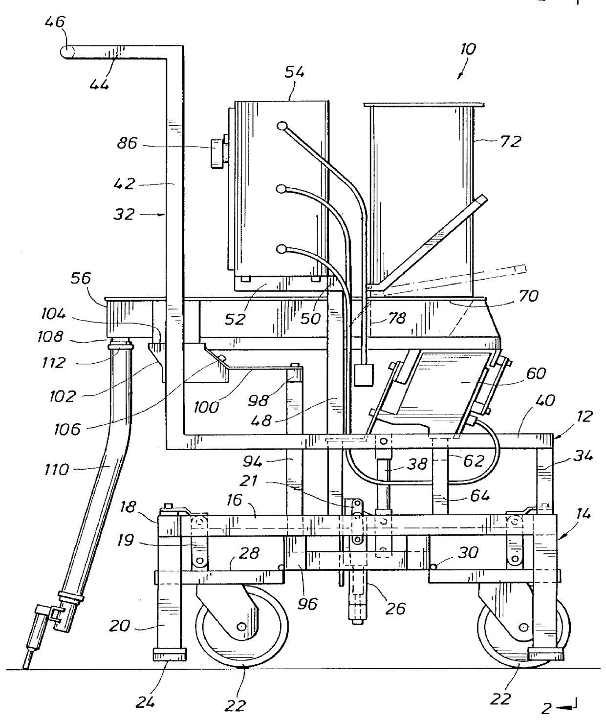
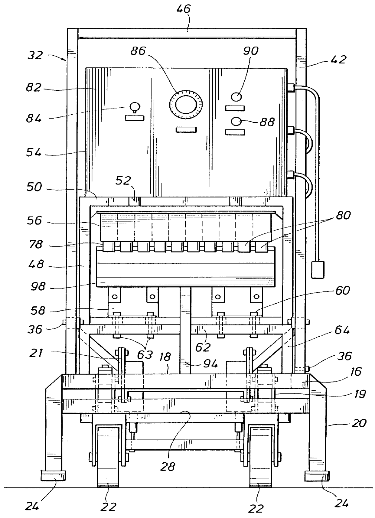
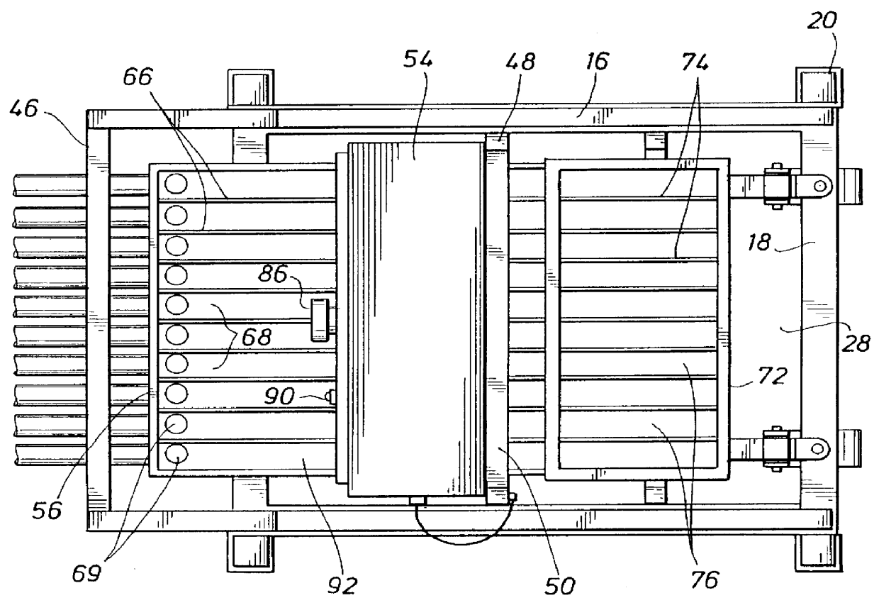
Referring now to the drawings and first to FIGS. 1-3, a mechanized catalyst loading cart that in constructed in accordance with the principles of the present invention is shown generally at 10 and incorporates a cart framework, shown generally at 12, having a wheeled base structure shown generally at 14. The wheeled base 14 is in the form of a rectangular framework base having side members 16 and end members 18 from which depend support legs 20 that are located at respective corners of the rectangular base. The wheeled base structure 14 is provided with a plurality of casters 22 which enable the cart to be rolled along any horizontal surface, such as the horizonal upper tube sheet of a catalytic reactor. To isolate the vibration of the loading cart mechanism from the upper tube sheet of the reactor, cushioned feet 24 are provided for each of the legs 20. These cushioned feet rest upon the upper tube sheet of the reactor after the cart has been properly located for dispensing of cata...


PUM

PropertyMeasurementUnit
Weightaaaaaaaaaa
Timeaaaaaaaaaa
Volumeaaaaaaaaaa

Abstract

A catalyst loading system for utilizing catalyst from a bulk supply located adjacent but not on the upper tube sheet of a catalytic reactor and for mechanized measuring of multiple identical quantities of catalyst and for mechanized loading of catalyst pellets into the reaction tubes of the reactor to achieve even drop rate, compaction and outage of the reaction tubes. A pair of electronic vibrators are mounted to the cart framework and provide for support and vibratory movement of a vibratory tray having a catalyst feed hopper adapted to feed catalyst pellets to a plurality of generally parallel catalyst transfer troughs along which catalyst pellets are moved by vibration of the vibratory tray to a plurality of drop tubes. A compartmented hopper is fixed to the vibratory tray and controllably feeds catalyst pellets into respective catalyst transfer troughs. A plurality of charging tubes are connected to respective drop tubes by a plurality of elongate flexible tubes and are maintained in fixed, spaced relation by a structural element so as to define a charging manifold for simultaneous, timed delivery of catalyst pellets into a plurality of reactor tubes. The charging manifold which can be raised and lowered has locator pins which are inserted into selected reactor tubes for orienting the charging tubes of the charging manifold with respect to a selected group of reaction tubes. An electronic control system controls the vibrators responsive to catalyst weight to achieve even catalyst drop rate during an entire catalyst charging cycle.

Description

1. Field of the InventionThis invention relates generally to the controlled filling of the catalyst tubes of catalytic reactors with catalyst materials when the reactors are placed into service or when they have been cleaned of spent catalyst materials in preparation for further use in processes requiring catalytic reaction of flowing products of the process. More particularly, the present invention concerns a mechanized catalytic reactor charging system including a loading cart that is used by reactor servicing personnel and which is effective for efficient and controlled and simultaneous charging of a plurality of the reaction tubes of a catalytic reactor so that each of the plurality of reaction tubes will contain a precise measured quantity of the catalyst arranged in one or more layers and having a predetermined degree of compaction. Even further, the present invention concerns a mechanized catalyst loading cart having the capability for automatically adjusting the amplitude of...

Claims


Application Information

Patent Timeline
IPC IPC(8): B01J8/00B01J8/02B01J8/06
CPCB01J8/002B01J8/003B01J8/06B01J8/0035B01J2208/00752
Inventor COMARDO, MATHIS P.
Owner COMARDO MATHIS P
Why Eureka
Try Eureka