Heart pacemaker

a heart and heart valve technology, applied in the field of heart valves, can solve the problems of intraventricular delay in the transmission of stimulating impulses to the left ventricle, loss of synchronous mechanical contraction of the left and right ventricles, and transvenous electrodes

Inactive Publication Date: 2000-11-07
GRAEMED PTY
View PDF6 Cites 301 Cited by
  • Summary
  • Abstract
  • Description
  • Claims
  • Application Information

AI Technical Summary

Benefits of technology

The base member preferably forms part of a hermetically sealed body comprising pulse generator circuitry and a power source for providing the pacing function. The entire body is preferably of such size that it can be placed at the apex of the heart in between the diaphragm and the heart. Surgical placement of such a device may be a fairly simple procedure and can preferably be performed by today's endoscopic techniques.
Preferably when in use the pacemaker substantially eliminates polarization at the or each stimulating electrode.

Problems solved by technology

Transvenous electrodes suffer from a number of problems one of which is a loss of synchronous mechanical contraction of the left and right ventricles.
This right ventricular pacing causes an intraventricular delay in the transmission of stimulating impulses to the left ventricle.
Conventional pacemakers using electrodes placed transvenous in the right ventricle of the heart also suffer from a number of other problems.
Relatively long conductive leads are used to connect the implanted electrode to the pulse generator and the electrode, requiring the generation of higher voltages and resulting in a large drain on the power source.
This shortens the life of the pacemaker.
This can be an expensive procedure, which in conventional transvenous electrodes, requires the provision of expensive equipment to perform fluoroscopy for positioning of the electrode.
The expense of the procedure limits application.
This, again, results in an increased drain on the power source.
Further, coupling the sensing and pacing functions in a single electrode results in the possibility of local polarization interfering with the sensing function.
Yet a further problem is movement of the electrode away from the original implantation side.
This results in the incorrect stimulation of the cardiac tissue.
Any error can lead to problems.
Further, the surgical procedure necessary to implant an electrode in the coronary sinus is complex and difficult.
Furthermore, Mower provides no solution to the problems of using single electrodes connected by relatively long leads.

Method used


Image

  • Heart pacemaker
  • Heart pacemaker
  • Heart pacemaker

Examples


Embodiment Construction

The contents of copending PCT Application No. AU92 / 00219 are incorporated herein by way of reference.

Embodiments and features of that application may be combined with those of the present invention.

In particular, alternate or reverse polarity pulsing of the electrodes may be applied.

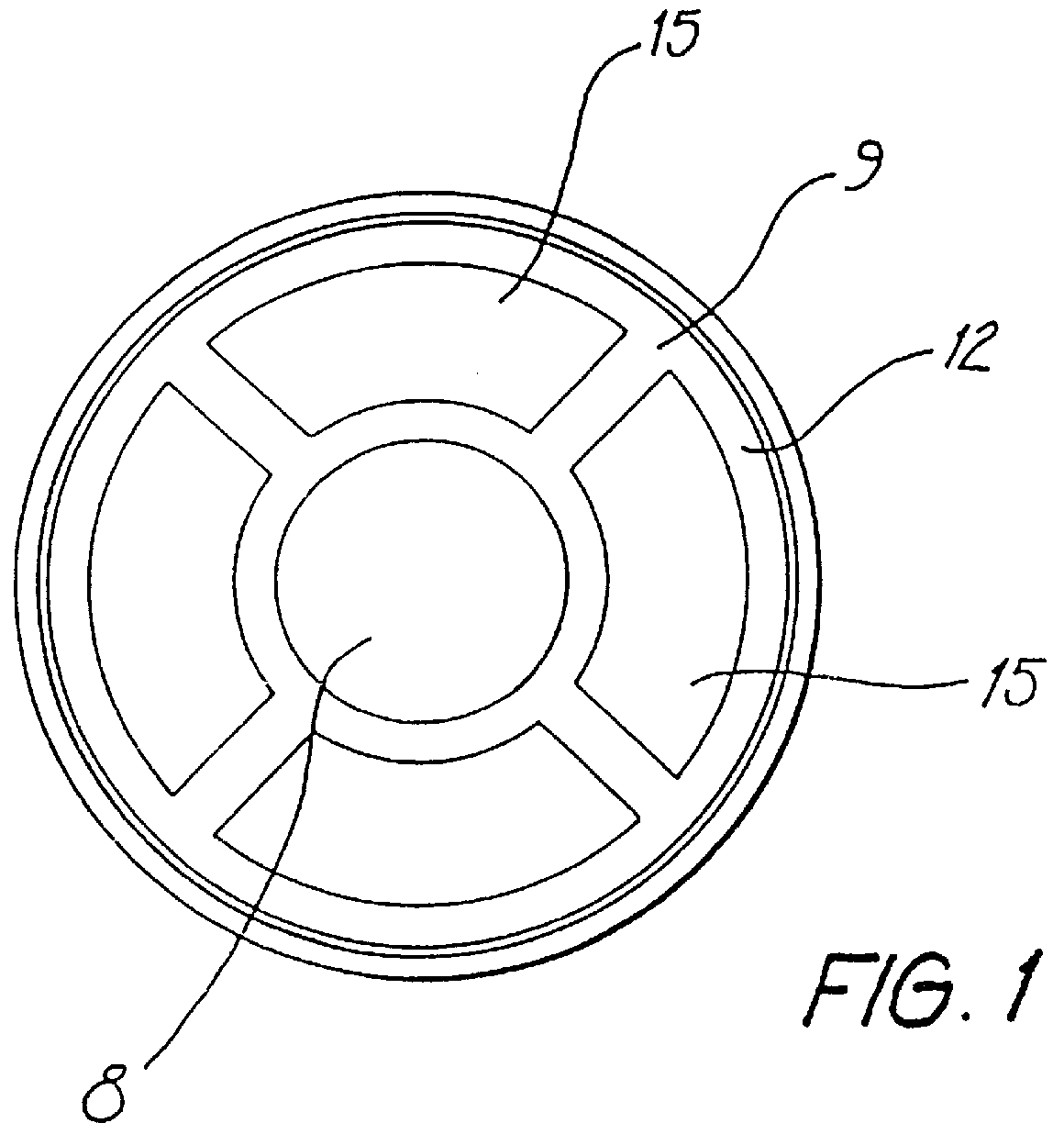
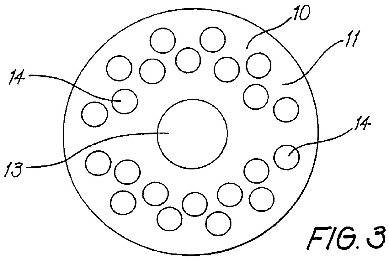
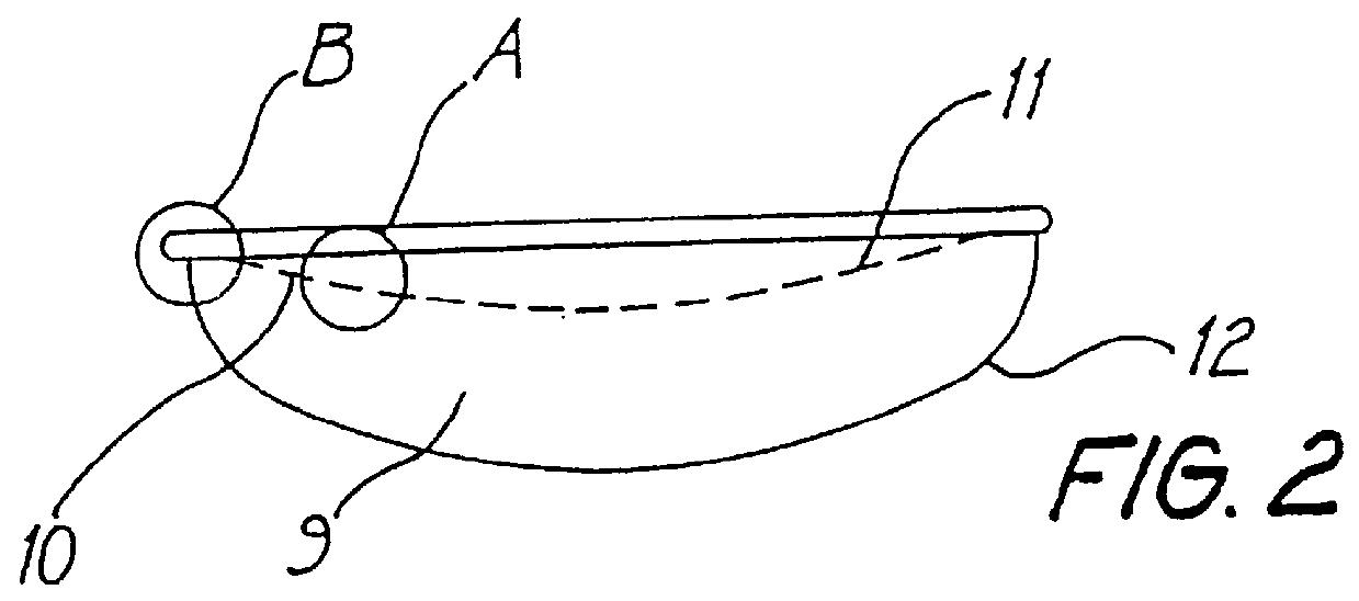
The pacemaker shown in FIGS. 1 to 3 is a self contained hermetically sealed unit which may be made of a resilient plastics material or a ceramic material. The pacemaker according to this first embodiment is part hemispherical in shape or dish-like and comprises a base member 10 having a concave surface 11 which forms the outer part of the surface a further housing member 9 having a convex surface 12 which opposes the concave surface 11. The two members 9 and 10 form a sealed container which houses electronic circuitry, comprising at least a pulse generator means, required to operate the pacemaker.

The concave surface 11 is shaped so that is will conform to the apical area of a heart at least to enable ele...


PUM


Abstract

A heart pacemaker which is arranged to stimulate the apical area of the heart. Stimulation of this area provides synchronous mechanical contraction of the left and right ventricles and overcomes the problem of pacemaker induced left bundle branch block type conduction disturbance. The pacemaker has a base surface which conforms to the apical area of the heart and mounts a plurality of epicardial stimulating electrodes. Selection of electrodes can be made to provide the most clinically appropriate stimulation. An opposite side of the pacemaker is arranged to contact the diaphragm and is provided with sensing electrodes to sense activity of the diaphragm and adjust pacing of the heart in accordance with changes in physical activity of the patient. The electrodes used are preferably of capacitive construction, having first and second capacitive plates either side of a dielectric formed by the body of the pacemaker.

Description

1. Field of the InventionThe present invention relates to a heart pacemaker.2. Description of the Prior ArtAn existing cardiac pacemaker consists of a power source and electronic circuitry which together constitute a pulse generator housed within a hermetically sealed metal capsule. The metal capsule is arranged to be inserted within a patients body normally near one of the pectoral muscles. An insulated lead having its proximal end connected into a receiving port of the metal capsule so as to provide a direct connection with the pulse generator, has its distal end connected to one or more bare metal electrodes which are located inside the patients heart. Typically, such transvenous electrodes are positioned in the right ventricle and deliver stimulating impulses to the endocardium. This was first successfully performed by Lagergren et al. at the Karolinska Institute in Stockholm, Sweden, 1962. Prior to this the stimulating electrodes were attached to the epicardium by thoracotomy f...

Claims


Application Information

Patent Timeline
Patent Type & Authority Patents(United States)
IPC IPC(8): A61N1/375A61N1/05A61N1/372A61N1/362A61N1/365
CPCA61N1/0587A61N1/362A61N1/3686A61N1/375A61N1/36542A61N1/3756A61N1/37512
Inventor GRAY, NOEL DESMOND
Owner GRAEMED PTY
Why Eureka
Try Eureka