Non-spilling detachable pouring spout

a pouring spout and detachable technology, applied in the direction of liquid transfer devices, liquid handling, packaging goods types, etc., can solve the problems of container overflow, liquid can be spilled from the pouring spout, and it is difficult to know when the container being filled becomes full

Inactive Publication Date: 2000-12-05
DSD INT INC
View PDF15 Cites 69 Cited by
  • Summary
  • Abstract
  • Description
  • Claims
  • Application Information

AI Technical Summary

Problems solved by technology

During the tipping operation however, liquid can be spilled from the spout before it is properly positioned relative to the filling neck.
With known spouts it is also difficult to know when the container being filled becomes full.
Often the container overflows because the person filling the container cannot see past the spout in the filling neck.
Furthermore, when transferring volatile and highly inflammable liquid, dangerous gaseous vapours escape from the receiving container.
All these problems raise significant safety concerns with known spouts.
This can results in dangerous explosions for the home owner refuelling his lawn mower, skin contamination for the farmer handling pesticides and herbicides, and injury for persons using liquids which are harmful upon contact with the skin, such as acid.
However, much of the known spouts which can be attached to a filling container do not address or offer an effective solution to the problem of spillage due to overflowing.
Additionally, these known spouts do not resolve the problem of liquid spillage due to liquid left in the dispensing tube between the valve an the outlet end of the tube.
Further, the known valve equipped spouts do not provide a locking mechanism which prevents accidental valve opening, neither they provide means for preventing evaporation.
However, this spout does not provide means regulating an airflow for preventing spillage of liquid when the receiving container is full, neither it resolves the problem of liquid evaporation.
However, this spout do not provide an air regulating means allowing air to flow from a downstream end of the outlet tube inserted inside the receiving container, up into the filling container thereby preventing spillage of liquid when the receiving container is full.
It does not either provide a solution to the problem of evaporation.

Method used


Image

  • Non-spilling detachable pouring spout
  • Non-spilling detachable pouring spout
  • Non-spilling detachable pouring spout

Examples


Embodiment Construction

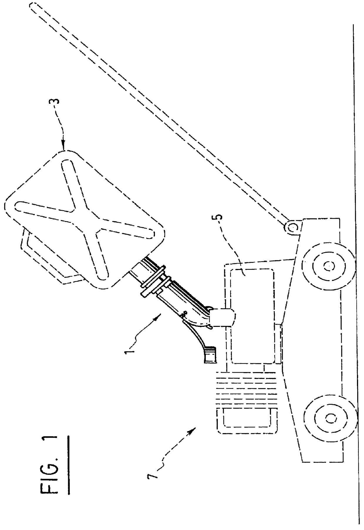
A pouring spout 1 according to the invention, is devised for transferring liquid from a filling container 3 to a receiving container 5. For example, as shown in FIG. 1, the pouring spout can be permanently or detachably mounted on a container 3 to fill a small tank 5 on a lawn mower 7 with gasoline.

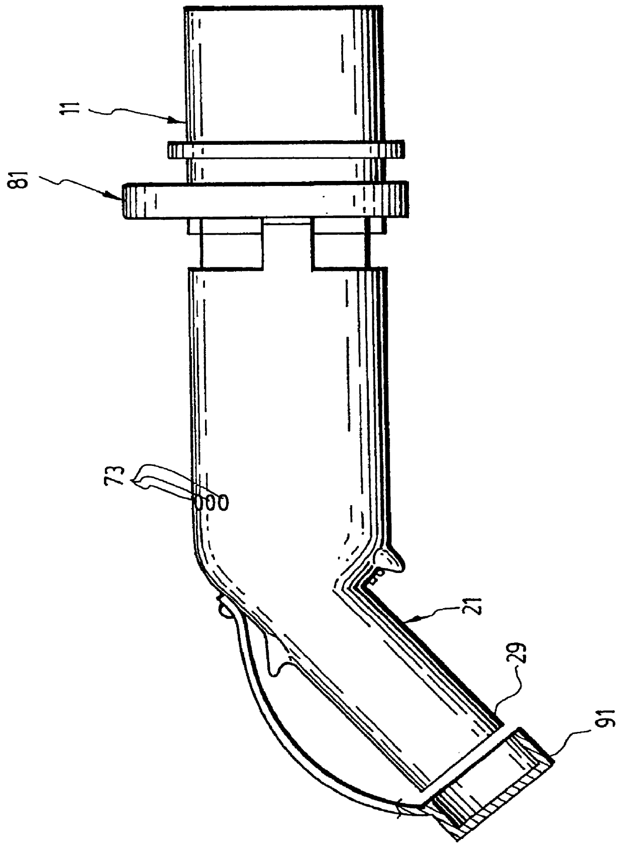
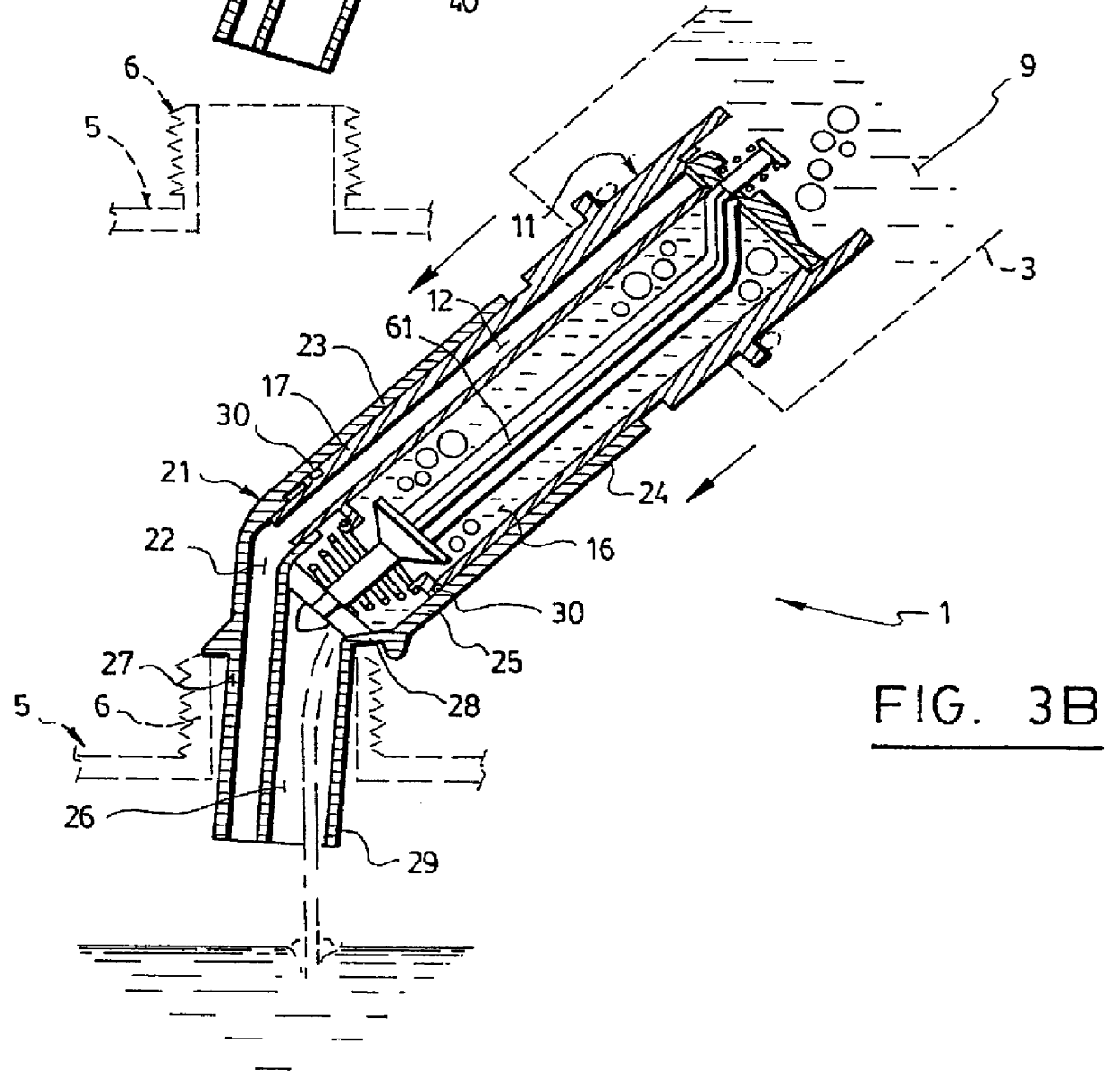
As shown in FIG. 3A, the pouring spout 1 comprises an inlet tube 11, and an outlet tube 21. The inlet tube 11 has an inlet portion 13 with an upstream end 14 and a downstream end 15 and a main portion 17 with an upstream end 18 and a downstream end 19. The downstream end 15 of the inlet portion 13 is adjacent to the upstream end 18 of the main portion 17. The inlet tube 11 also comprises an air channel 12 and a liquid channel 16 which extend inside the inlet tube 11 from the upstream end 14 of the inlet portion 11 to the downstream end 19 of the main portion 17. Furthermore, the inlet portion 13 is provided with or operatively connected with suitable connecting means 10 for attaching the ...


PUM

PropertyMeasurementUnit
angleaaaaaaaaaa
pressureaaaaaaaaaa
distanceaaaaaaaaaa

Abstract

This invention relates to an improved pouring spout of the type of ones which are detachably connected to a filling container for transferring liquid in a receiving container. These kind of pouring spout include an inlet tube for receiving liquid from the filling container, and an outlet tube telescopically mounted to slide onto the inlet tube for guiding liquid therefrom into the receiving container. The spout also comprises a liquid valve which opens and closes automatically upon sliding of the outlet tube. The current invention further comprises an air passage and an air valve for regulating an air flow inside the spout from the receiving container into the receiving container, such that the flow of liquid inside the spout stops automatically when the receiving container is full, thereby avoiding spillage of liquid. The pouring spout of the invention also resolve the problem of emanations related to the transfer of dangerous volatile and highly inflammable liquid.

Description

a) Field of the InventionThe present invention relates to an improved non-spilling pouring spout which can be attached to most containers for use in pouring liquid from a filling container into a receiving container, with no risk of accidental spillage and / or evaporation.b) Brief Description of the Prior ArtPouring spouts on containers, for use in filling other containers or tanks with liquid, are well known. In use, the container with the spout is tipped to position the spout downwardly in a filling neck on the container to be filled. During the tipping operation however, liquid can be spilled from the spout before it is properly positioned relative to the filling neck. With known spouts it is also difficult to know when the container being filled becomes full. Often the container overflows because the person filling the container cannot see past the spout in the filling neck. More liquid can be spilled when the spout is withdrawn from the filling neck. Furthermore, when transferri...

Claims


Application Information

Patent Timeline
Patent Type & Authority Patents(United States)
IPC IPC(8): B67D5/01B67D7/00B67D7/06B67D7/42
CPCB67D7/005
Inventor VACHON, LEANDRE
Owner DSD INT INC
Why Eureka
Try Eureka