Arrangement for transferring heating and cooling power

a technology for transferring heating and cooling power and arrangement, which is applied in the direction of energy-efficient heating/cooling, stationary tubular conduit assemblies, stationary plate conduit assemblies, etc. it can solve the problems of inability to use much other heat generated in connection with electricity production, inability to reduce the cost of electricity production, etc., to achieve the effect of extending the length of the plate pack, reducing flow resistance, and new planning freedom

Inactive Publication Date: 2000-12-12
ABB POWER +1
View PDF22 Cites 54 Cited by
  • Summary
  • Abstract
  • Description
  • Claims
  • Application Information

AI Technical Summary

Benefits of technology

If the channel plates are preferably made into the shape of a square, that is, the size a=b, the flow surface is fourfold in comparison with the flow area of the apparatus of FI-95414. Furthermore, the distance the vapour flows between the channel plates will diminish by half, which will further lower flow resistance. This enables the use of a plate heat exchanger in an absorption aggregate where essentially lower pressures are present than in an apparatus producing salt-free water.
Another significant advantage will be attained by the loose placement. The flow rate of vapour restricts the length of the sides of the exchanger, or to be more exact, the ratio of the width of the slot between the channel plates and the side of the exchanger, which ratio should generally be more than 1:100. When the size of the channel plates cannot be enlarged, the only way in known apparatuses is to increase the number of channel plates, that is, extend the length of the plate pack. This is also restricted because of technical manufacturing problems, heat expansion and other such reasons. It would also be difficult to place the apparatus. Therefore the only way to build larger apparatuses is to build two or more separate heat exchangers connected in parallel.
In the solution of the invention, several exchangers can be positioned inside the same shell side by side, one on the other or one after the other, which gives totally new freedom for planning and leads to very effective space utilization. The costs of one large shell or container are, of course, also smaller than those of several small ones.
The loose and free placing of the heat exchangers inside the shell makes it also possible to reduce the size and costs of the aggregate essentially when it is understood that vapour can be conveyed in / taken out through openings placed at different points on the diameter.
The solution of the invention also makes it possible that the slots between the channel plates are made larger on the vapour side and / or expanding towards the diameter of the exchanger, which further improves the applicability as an absorption aggregate.

Problems solved by technology

With regard to production, the consumption also occurs at an unfavourable time.
The heat inevitably generated in connection with the production of electricity cannot be used for much else than production of hot tap water, and so it has to be condensed and supplied to waterways, e.g., by brine condensers or to air by cooling towers.
Absorption cooling systems have not become common, however, due to high investment costs.
Although the kWh price of the chill generated in this way is low as compared with the price of electricity, the number of hours of use is so small in those climatic zones where district heating systems have been built that the investment costs will not be covered.
In Finland, for example, such systems have thus not been built.
The need for space is triple in comparison with a compressor aggregate, for example, which further raises costs.
Low pressure vapour flowing in all parts of the absorption aggregate requires large flow paths, which increases the size of the apparatus and especially that of the heat exchangers.
The requirement of large flow paths has meant that it has not been possible to build absorption aggregates in district heating networks for ordinary boiling temperatures of 70 to 80.degree. C. as the size of the aggregate, as well as the costs of the aggregate, will grow too much because of low pressure.
A high boiling temperature is particularly disadvantageous to the use of solar collectors as their power will fall considerably if the temperature of the heat exchange liquid rises.
Their manufacture costs are, however, high as it is difficult to automatize manufacture, and the price / heat delivery surface-m.sup.2 of the raw material, i.e., of the pipes is high.
The small need for space of the plate heat exchangers has the drawback that the flow paths of the heating medium especially at the comers of the exchanger are very narrow.
Because of technical manufacturing reasons, they cannot be made to be very much larger either.
The apparatus shown above is not, however, suitable for absorption aggregates, for example, where one of the heat transfer media will evaporate or condense while the other will stay in liquid form.
Furthermore, the distance the vapour flows between the channel plates will diminish by half, which will further lower flow resistance.
This is also restricted because of technical manufacturing problems, heat expansion and other such reasons.
It would also be difficult to place the apparatus.
Even small leakages cause corrosion and impair heat transfer as leakage air will collect on heat transfer surfaces.

Method used


Image

  • Arrangement for transferring heating and cooling power
  • Arrangement for transferring heating and cooling power
  • Arrangement for transferring heating and cooling power

Examples


second embodiment

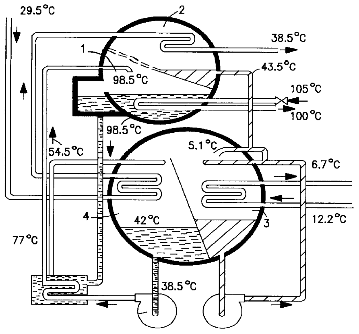
the invention is shown in FIG. 8. In order to save space, the shell 3 is made as small as possible and vapour is provided with flow paths 23, 23', 23" and 23'" on each side of the heat exchangers 1, 2. This requires that the division plate 25 can be made to be low as in FIG. 8. This application uses square-shaped heat exchangers 1, 2 which have two pairs of connector pipes.

If the dividing plate 25 is low, the liquids in the absorption part and the evaporator may get mixed. This risk can be eliminated by forming the lower part of the shell 3 into a liquid receiver 26 that can act as a support element of the aggregate at the same time. This application is shown in FIG. 9.

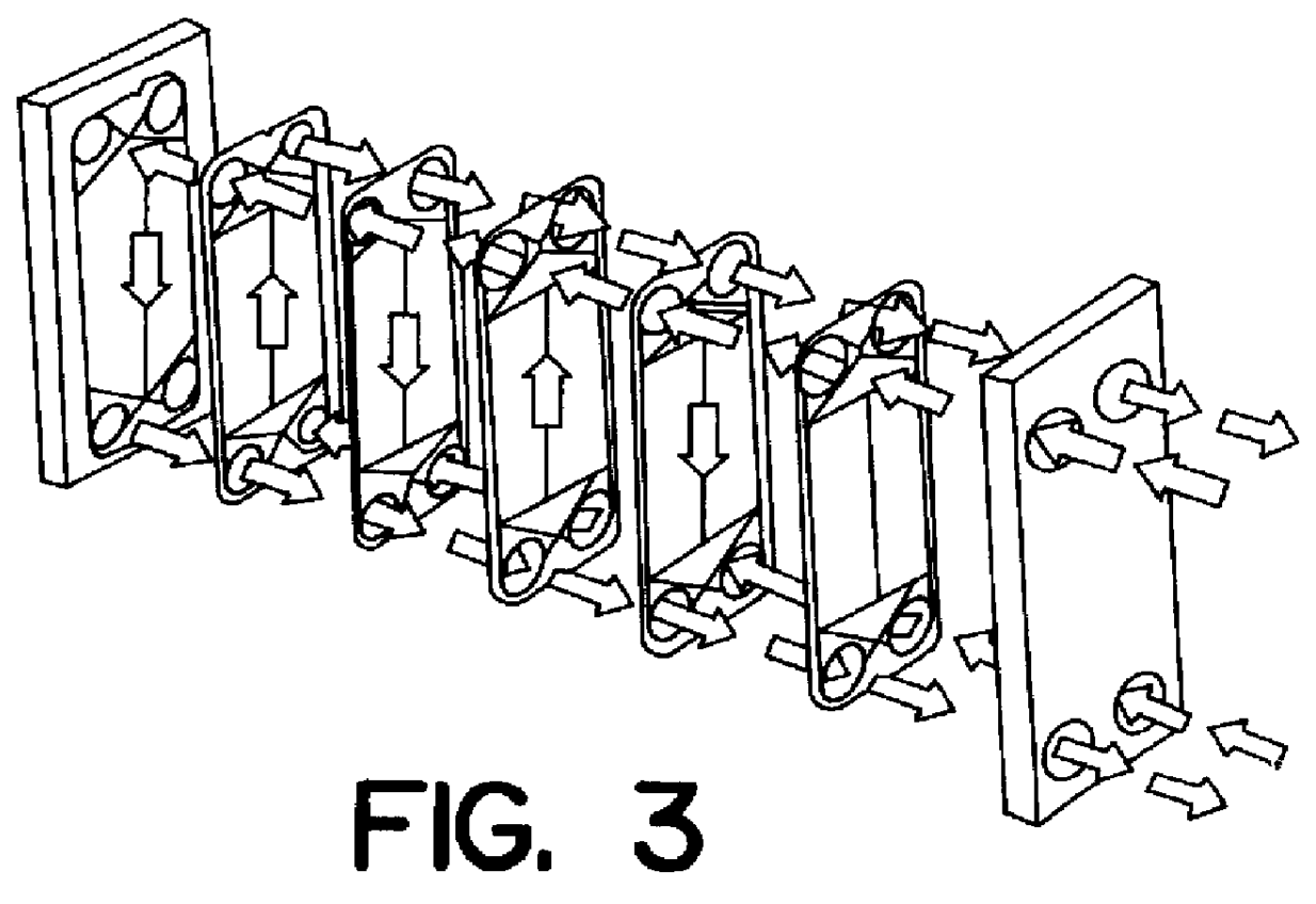
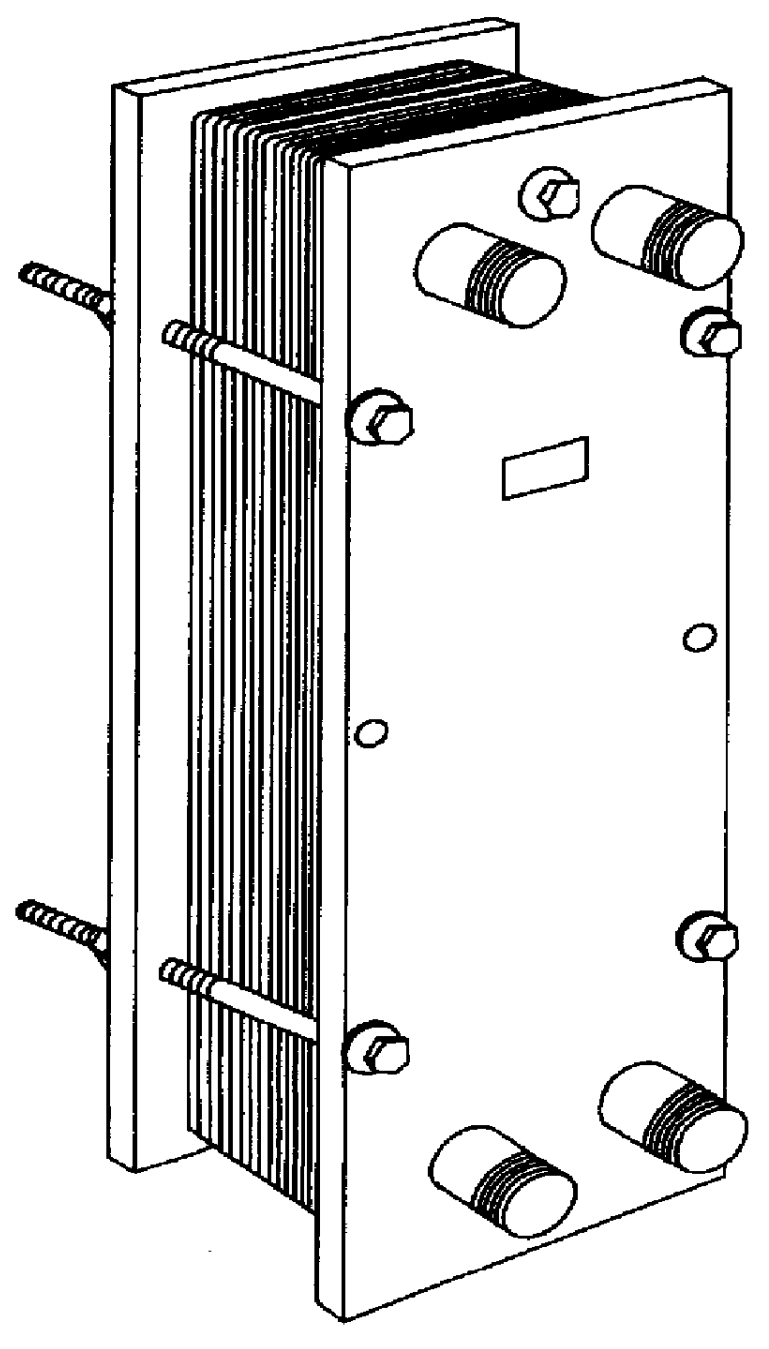
Large units can be built as shown in FIG. 10 by placing several heat exchangers side by side, one on the other and / or one after the other inside one shell 3. In the application of FIG. 10, liquid films are formed on heat exchange surfaces of the exchangers by nozzles 28 fixed to nozzle pipe systems 27. Overflow liquid...


PUM


Abstract

PCT No. PCT/FI97/00515 Sec. 371 Date Mar. 31, 1999 Sec. 102(e) Date Mar. 31, 1999 PCT Filed Sep. 3, 1997 PCT Pub. No. WO98/10233 PCT Pub. Date Mar. 12, 1998An apparatus for transferring heating and cooling power by means of two heat transfer media, wherein at least one of the heating media is arranged to be evaporated or condensed. To reduce the need for space, the apparatus includes a shell (3) inside which at least one plate heat exchanger (1,2) is arranged loosely, flow slots (19) of the heat exchanger being arranged to be completely or mainly open towards the shell (3) in such a manner that the evaporating or condensing heat transfer medium can flow to the plate heat exchanger or from the plate heat exchanger from different sides of the plate heat exchanger on the whole length of that slot (19) which is open.

Description

1. Field of the InventionThe invention relates to an arrangement (apparatus) for transferring heating and cooling power by means of two heat transfer heating media, in which arrangement at least one of the heat transfer media is arranged to be evaporated or condensed.2. The Prior ArtAbsorption aggregates have long been used for transferring thermal energy from one energy level to another, or in other words, for producing heating or cooling power on a useful temperature level from a source not on a useful level. The operation of absorption aggregates is based on that possible because specific absorption agents are capable of absorbing to themselves specific other agents at a higher temperature than the boiling point of the agent under the prevailing pressure. In other words, they are able to bind to liquid another vaporous agent at a temperature higher than the boiling point of the agent in question. These agents, i.e., agents forming an absorption pair, can be separated again from o...

Claims


Application Information

Patent Timeline
Patent Type & Authority Patents(United States)
IPC IPC(8): F28F3/08F25B15/02F28D9/00F25B15/06F25B39/02F25B39/04F25B15/00
CPCF25B15/06F28D7/0058F28D7/08F28D9/0006F28F1/32F28F3/083F28F13/08F28D9/0093Y02B30/62F28F2250/102Y02A30/27F28D9/00
Inventor LAMPINEN, MARKKUKONTU, MAURI
Owner ABB POWER
Why Eureka
Try Eureka