
Capacitively readout multi-element sensor array with common-mode cancellation

Inactive Publication Date: 2001-01-02
LOCKHEED MARTIN ENERGY SYST INC +1
View PDF44 Cites 76 Cited by
  • Summary
  • Abstract
  • Description
  • Claims
  • Application Information

AI Technical Summary

Benefits of technology

It is yet a further object of the present invention to provide an apparatus which is capable of providing an output signal reflective of the accumulation of a chemical, physical or biological presence sought to be detected.
It is yet another object of the present invention to provide an apparatus which is capable of providing an output signal free from the effects of stray capacitance and common-mode noises.

Problems solved by technology

To date, however, available technology has limited the use of cantilevers to a single read out, normally by optical beams.
This use is cumbersome and time consuming.

Method used


Image

  • Capacitively readout multi-element sensor array with common-mode cancellation
  • Capacitively readout multi-element sensor array with common-mode cancellation
  • Capacitively readout multi-element sensor array with common-mode cancellation

Examples


first embodiment

OPERATION OF THE INVENTION

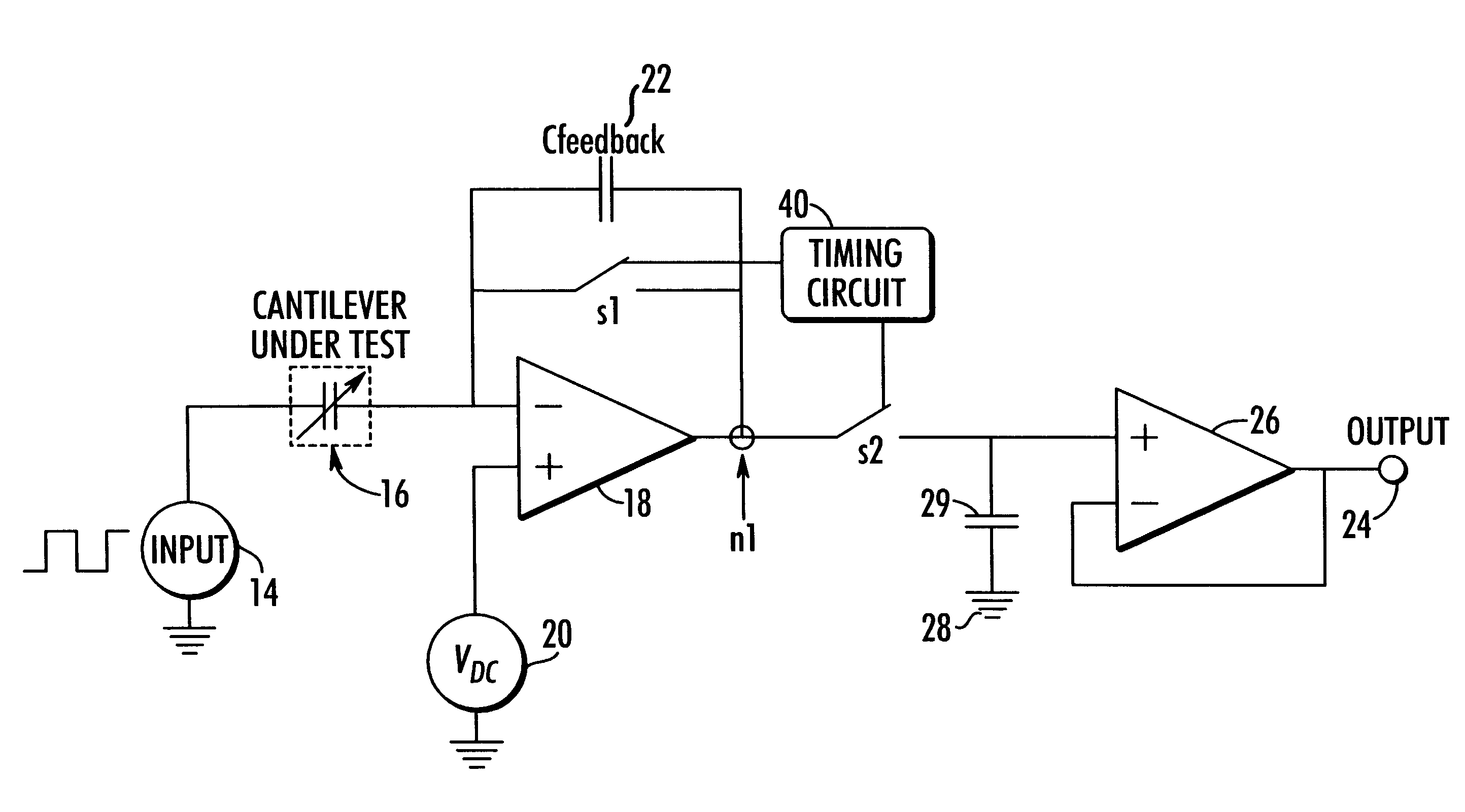
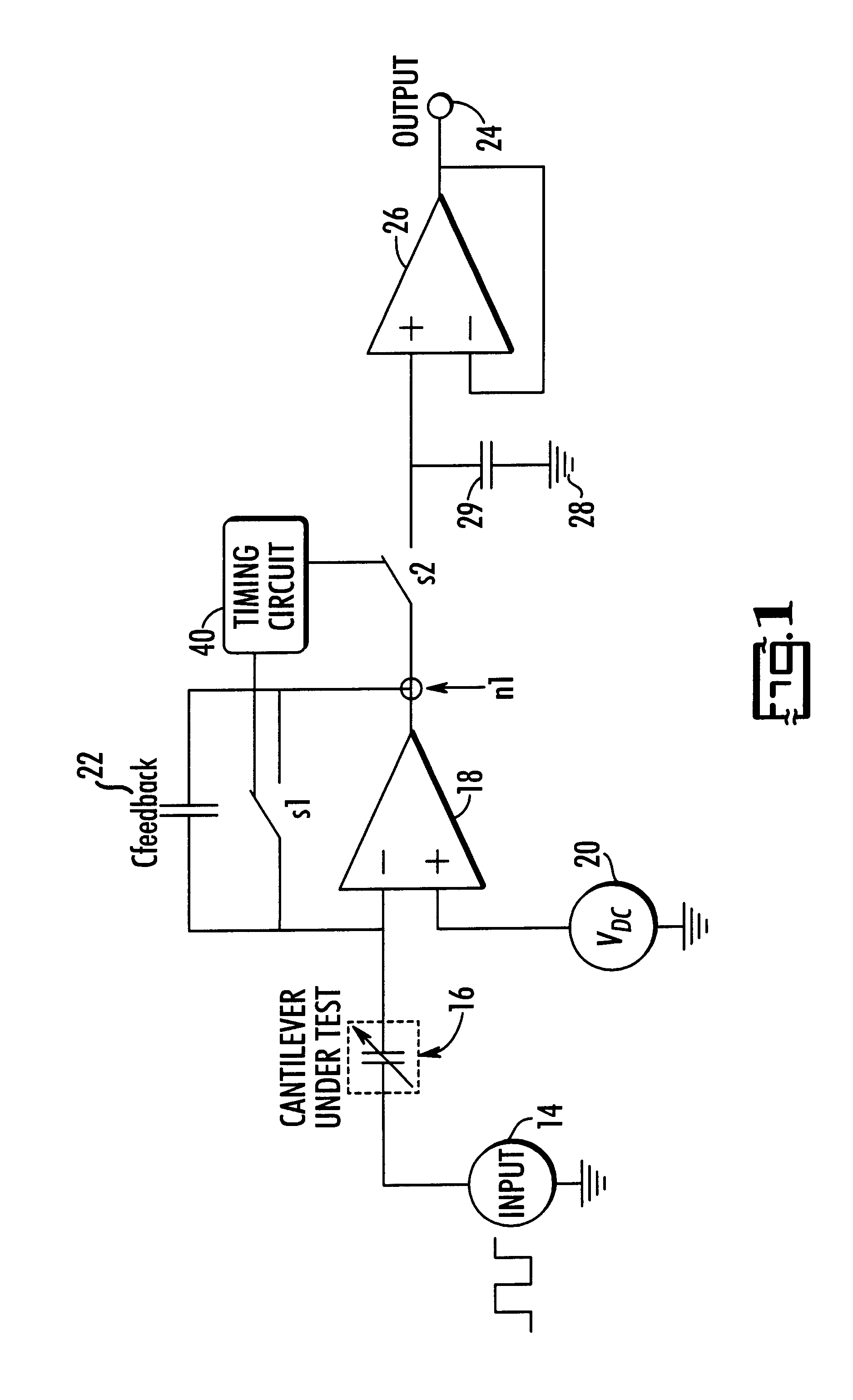
In further detailing the operation of the apparatus and describing a first embodiment of the invention, we now turn to FIG. 2. As seen in Column A of FIG. 2, the apparatus 1 of FIG. 1 is provided as an array of cantilevers, thus Channel 1 through Channel (n+1) are provided. In a preferred embodiment, a single voltage input 14 may be provided for the array of cantilevers although separate inputs for each cantilever may be utilized without compromising the results of the invention.

At the bottom of Column A, the reference cantilever channel 30 is provided. The signal from reference cantilever channel 30 is made available to the processing elements in column B of FIG. 2. The capacitance produced by the sensor element providing input to channel 30 is produced by an arrangement similar to the arrangement of sensor 16, however, the cantilever associated with reference channel 30 is a non-coated cantilever or a cantilever having a coating unaffected by or minimally...

second embodiment

the present invention is further detailed in FIG. 3. As seen in FIG. 3, Column A, apparatus 1 is provided as an array of cantilevers, thus Channel 1 through Channel (n+1) are provided. A single voltage input 14 may be provided for the array, although separate inputs may be utilized without affecting the output of apparatus 1.

At the bottom of Column A, the reference cantilever channel 30 is provided. The signal from reference cantilever channel 30 is made available to the processing elements in column B of FIG. 3, the signal first passing through a level shifting buffer positioned between Column A and Column B. The capacitance produced by the sensor element providing input to reference 10. cantilever channel 30 is produced by an arrangement similar to the arrangement of sensor 16. The cantilever associated with reference channel 30, however, is a non-coated cantilever or a cantilever having a coating unaffected by or minimally affected by the presence or component being detected.

Colu...


PUM

PropertyMeasurementUnit
Timeaaaaaaaaaa
Electric potential / voltageaaaaaaaaaa
Areaaaaaaaaaaa

Abstract

An improved multi-element apparatus for detecting the presence of at least one chemical, biological or physical component in a monitored area comprising an array or single set of the following elements: a capacitive transducer having at least one cantilever spring element secured thereto, the cantilever element having an area thereof coated with a chemical having an affinity for the component to be detected; a pick-up plate positioned adjacent to the cantilever element at a distance such that a capacitance between the cantilever element and the pick-up plate changes as the distance between the cantilever element and the pick-up plate varies, the change in capacitance being a measurable variation; a detection means for measuring the measurable variation in the capacitance between the cantilever element and the pick-up plate that forms a measurement channel signal; and at least one feedback cantilever spring element positioned apart from the coated cantilever element, the cantilever element substantially unaffected by the component being monitored and providing a reference channel signal to the detection means that achieves a common mode cancellation between the measurement channel signal and reference channel signal.

Description

The present invention relates to instruments for measuring the concentration of a chemical, physical or biological presence or component dispersed within a monitored area. Specifically, the invention relates to a microcantilever sensor which measures the concentration of a chemical, physical or biological presence or component dispersed within a monitored area.A pressing need exists in many industries, disciplines and governmental interests for a highly sensitive and selective detector of quantifying chemical, physical or biological presences or components in a monitored area. To qualify, such a detector must have such diverse characteristics as being small, rugged, inexpensive, selective, reversible and extremely sensitive. Applicants have invented other apparatuses directed to this pressing need in the industry. U.S. Pat. No. 5,719,324 to Thundat and U.S. Pat. No. 5,445,008 to Wachter, incorporated herein by reference and commonly assigned to Applicant, both describe such technolo...

Claims


Application Information

Patent Timeline
IPC IPC(8): G01B7/16G01N27/00G01N27/22G01N19/10G01M3/04G01N27/24G01B7/34G01D5/12G01N19/00G01D5/241G01N33/543
CPCG01B7/023G01D5/2417G01N27/227Y10S436/806
Inventor BRITTON, JR., CHARLES L.WARMACK, ROBERT J.BRYAN, WILLIAM L.JONES, ROBERT L.ODEN, PATRICK IANTHUNDAT, THOMAS
Owner LOCKHEED MARTIN ENERGY SYST INC
Features
  • Generate Ideas
  • Intellectual Property
  • Life Sciences
  • Materials
  • Tech Scout
  • Unparalleled Data Quality
  • Higher Quality Content
  • 60% Fewer Hallucinations
Learn More