Bit error measuring device for modem device and bit error measuring method for the same

a modem device and measurement method technology, applied in the direction of digital transmission, marginal checking, instruments, etc., can solve the problem that the control of stopping or retransmitting the test pattern signal cannot be carried out in accordance with the flow control cod

Inactive Publication Date: 2001-01-02
YOKOGAWA ELECTRIC CORP
View PDF2 Cites 5 Cited by
  • Summary
  • Abstract
  • Description
  • Claims
  • Application Information

AI Technical Summary

Benefits of technology

Thereby, error bits are not transmitted to the units to which the test pattern signal is transmitted. Further, the test pattern signal can be stopped in accordance with the state of the stop bit, and can be transmitted by synchronizing with the synchronizing clock. The bit error measuring unit can avoid judging that the flow control codes are bit errors, and the bit error measuring device for a modem device, which can carry out the flow control can be provided. As a result, the present invention can provide a high performance and high reliability bit error measuring device.
Thereby, error bits are not transmitted to the units to which the test pattern signal is transmitted. Further, the test pattern signal can be stopped in accordance with the state of the stop bit, and can be transmitted by synchronizing with the synchronizing clock. The bit error measuring circuit can avoid judging that the flow control codes are bit errors, and the bit error measuring device for a modem device, which can carry out the flow control can be provided. As a result, the present invention can provide a high performance and high reliability bit error measuring device.

Problems solved by technology

However, because a flow control code outputted from a modem device cannot be detected, there is a problem that a control of stopping or retransmitting the test pattern signal cannot be carried out in accordance with the flow control code.

Method used


Image

  • Bit error measuring device for modem device and bit error measuring method for the same
  • Bit error measuring device for modem device and bit error measuring method for the same
  • Bit error measuring device for modem device and bit error measuring method for the same

Examples


Embodiment Construction

Hereinafter, an embodiment of the bit error measuring device for a modem device and bit error measuring method for the same according to the present invention will be explained in detail with reference to the attached drawings.

FIGS. 1 to 3 show an embodiment of the bit error measuring device for a modem device according to the present invention.

First, the construction of the bit error measuring device will be explained.

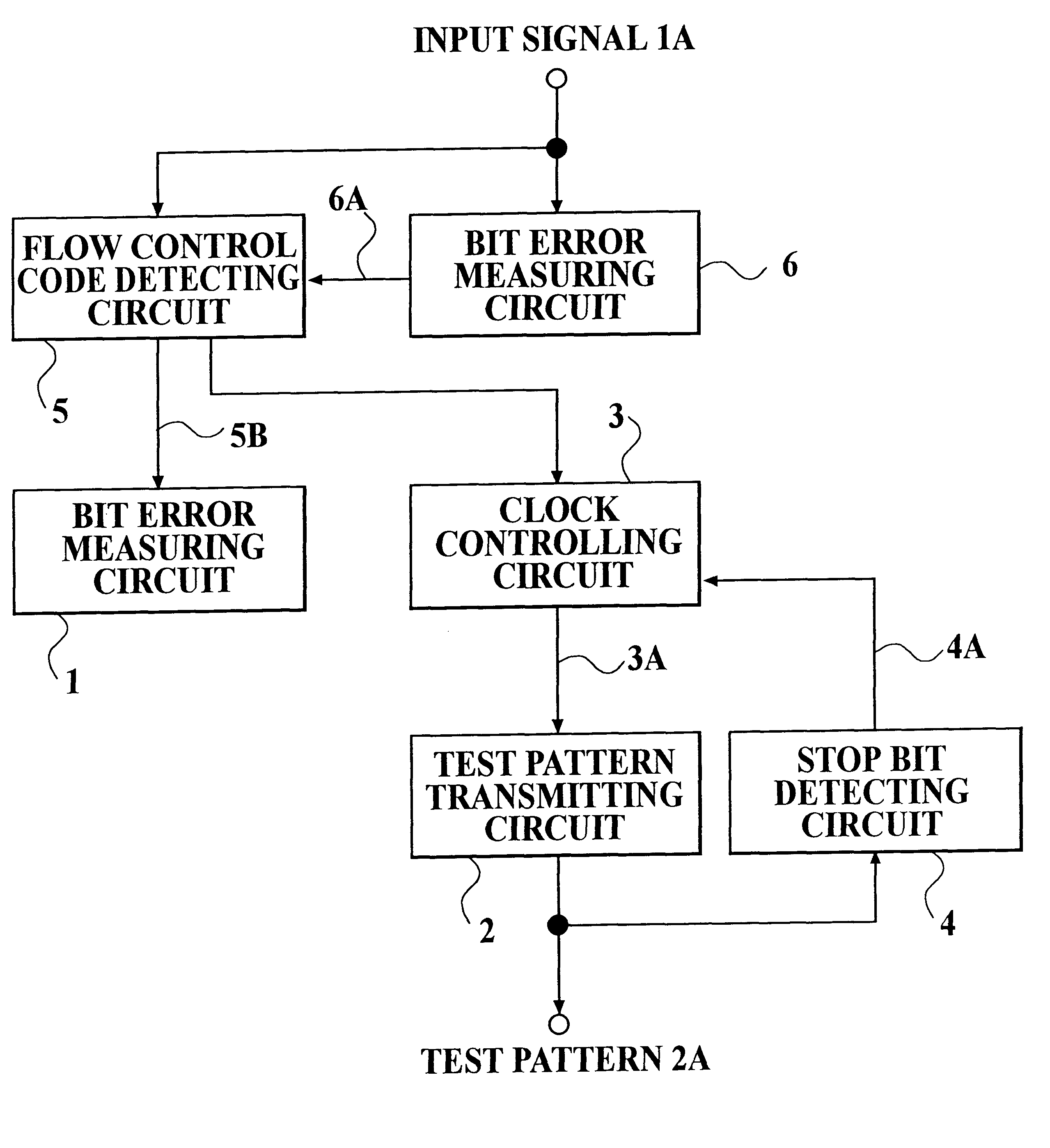
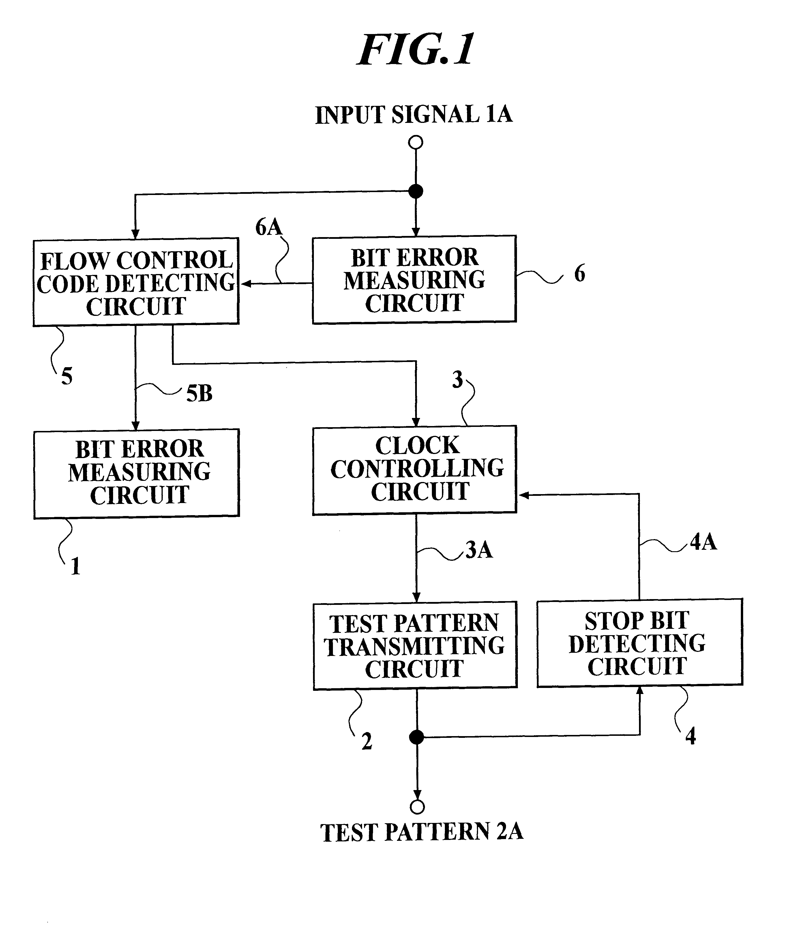
FIG. 1 is a block diagram showing a circuit construction of an embodiment of bit error measuring device. In FIG. 1, the bit error measuring device comprises a bit error measuring circuit 1, a test pattern transmitting circuit 2, a clock controlling circuit 3, a stop bit detecting circuit 4, a flow control code detecting circuit 5 and a bit error detecting circuit 6.

The bit error measuring circuit 1 measures (or detects) a bit error in an input signal 1A by using a signal 5B for measuring a bit error. The input signal 1A which is a pseudo-random pattern recommended by ...


PUM


Abstract

A bit error measuring device for modem device, comprises; a control code detecting unit for detecting a flow control code set in an input signal from the modem device, and for masking the flow control code, a bit error measuring unit for measuring bit errors in the input signal of which the flow control code is masked, a clock controlling unit for controlling an output of a clock signal by the flow control code, and a test pattern transmitting unit for transmitting a test pattern signal by synchronizing with the clock signal when clock pulses of the clock signal are outputted from the clock signal controlling unit, and for stopping a transmission of the test pattern signal when the clock pulses of the clock signal are not outputted from the clock signal controlling unit.

Description

1. Field of the InventionThe present invention relates to a bit error measuring device for a modem device and a bit error measuring method for the same, which can detect a flow control code outputted from a modem device connected with a data processing device through a connector, for example, an RS-232-C connector standardized by Electronic Industries Association, and which can control a transmission of a test pattern and can mask the flow control code, when a bit error measurement is carried out.2. Description of the Related ArtFIG. 4 shows a construction of a typical bit error measuring device for a modem device, which is connected with a data processing device, such as a personal computer, through an RS-232-C connector. The construction of the bit error measuring device will be explained. In FIG. 4, the bit error measuring device comprises a bit error measuring circuit 21, a test pattern transmitting circuit 22 and a clock controlling circuit 23.The bit error measuring circuit 21...

Claims


Application Information

Patent Timeline
Patent Type & Authority Patents(United States)
IPC IPC(8): G06F11/24G06F13/00H04L1/00H04L7/00
CPCG01R31/3171G06F11/24
Inventor OHTANI, MORITOSUZUKI, TAKAO
Owner YOKOGAWA ELECTRIC CORP
Why Eureka
Try Eureka