Fluid flow regulating valve and method

Inactive Publication Date: 2001-01-09
LUK GETRIEBE SYST
View PDF8 Cites 44 Cited by
  • Summary
  • Abstract
  • Description
  • Claims
  • Application Information

AI Technical Summary

Benefits of technology

One feature of the instant invention resides in the provision of a volumetric fluid flow regulating valve which comprises a body or housing having a passage (e.g., an elongated bore or hole), at least one inlet arranged to receive pressurized hydraulic fluid from a suitable source (e.g., an oil pump), a first outlet connectable to a reservoir (e.g., to a sump), and a second outlet. The improved valve further comprises a valving element (such as an elongated piston) which is reciprocable in the passage and has first and second end portions respectively adjacent first and second chambers forming part of the aforementioned passage. The valving element is movable relative to the housing between first and second positions in which the first and second outlets respectively receive fluid from the at least one inlet of the valve housing. Still further, the valve comprises energy storing means (e.g., a single coil spring) provided in the first chamber to bias the valving element in a direction to reduce the volume of the second chamber, means (e.g., a first conduit) for connecting the at least one inlet or the second outlet (in the second position of the valving element) with the second chamber so that the flui

Problems solved by technology

Any changes (shifting) of the input parameter can exert a negative influence upon the operation of the system, primarily because a shifting of the input parameter prevents the establishment of an optimum or desirable volumetric flow.
This, in turn, results in the establishment of an excessive pressure differential between the chamber for the aforementioned spring or springs at one axial end, and a second chamber at the aforementioned outlet (to the fluid circulating arrangement) of the housing in spite of the pressure drop which is caused by the flow restrictor, when the aforementioned pressure differential exceeds a certain value.
Such leakage results in a shifting of the operating point, and the end result is a change in the operation of the consumer or consumers.
Since the piston and the valve body are normally made of a metallic material, frequently recurring movements of the piston entail the development of pronounced wear, especially at the locations where the piston is to sealingly engage the surface bounding te passage in the valve housing.
The development of wear upon the piston and/or upon the valve housing aggravates the situation because it leads to a more pronounced leakage of fluid from the spring-confining chamber to the outlet of the pump housing.
Attempts to reduce the likelihood of wear upon the piston and/or upon the housing of the regulating valve, or to reduce the extent of such wear (e.g.

Method used


Image

  • Fluid flow regulating valve and method
  • Fluid flow regulating valve and method
  • Fluid flow regulating valve and method

Examples


Embodiment Construction

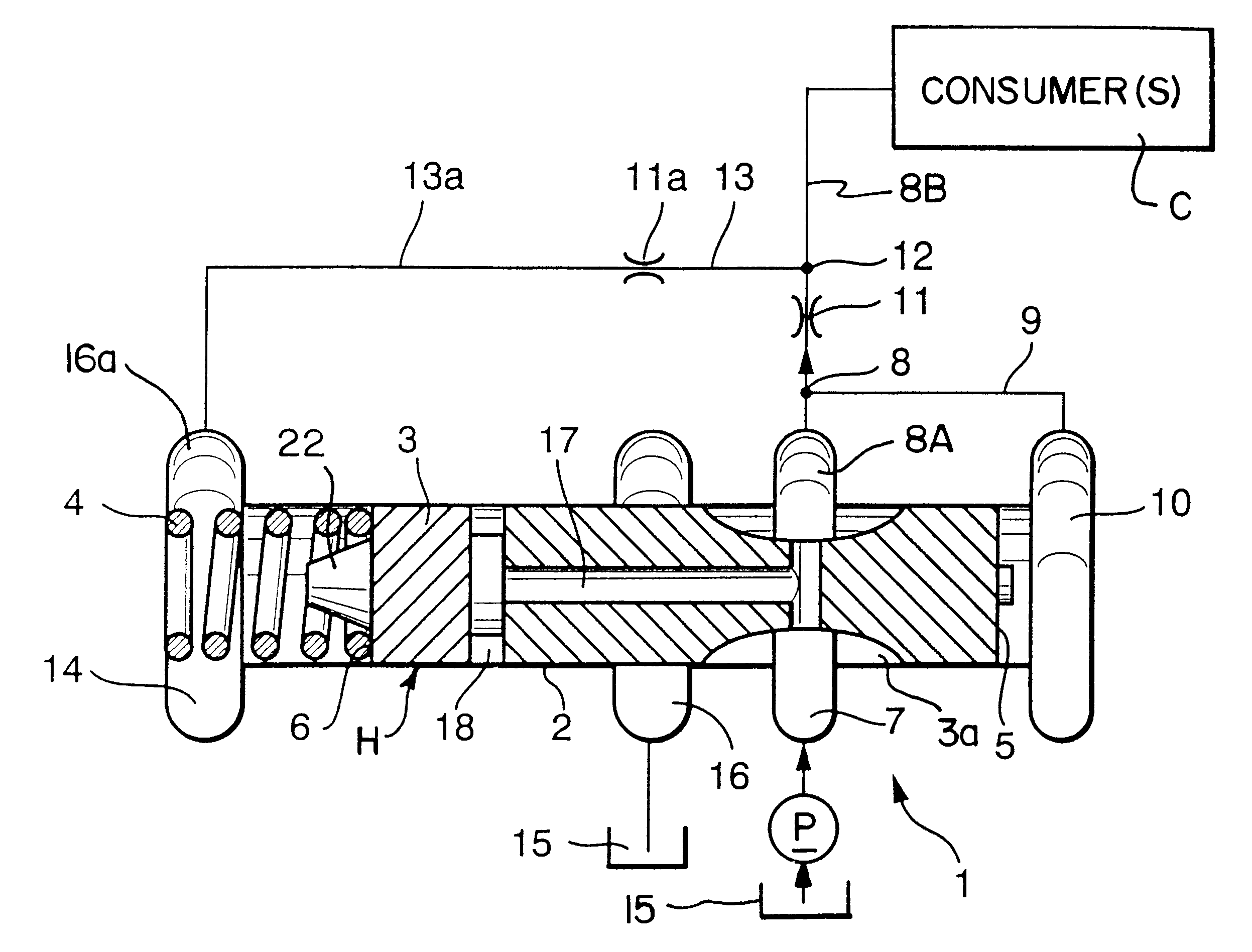
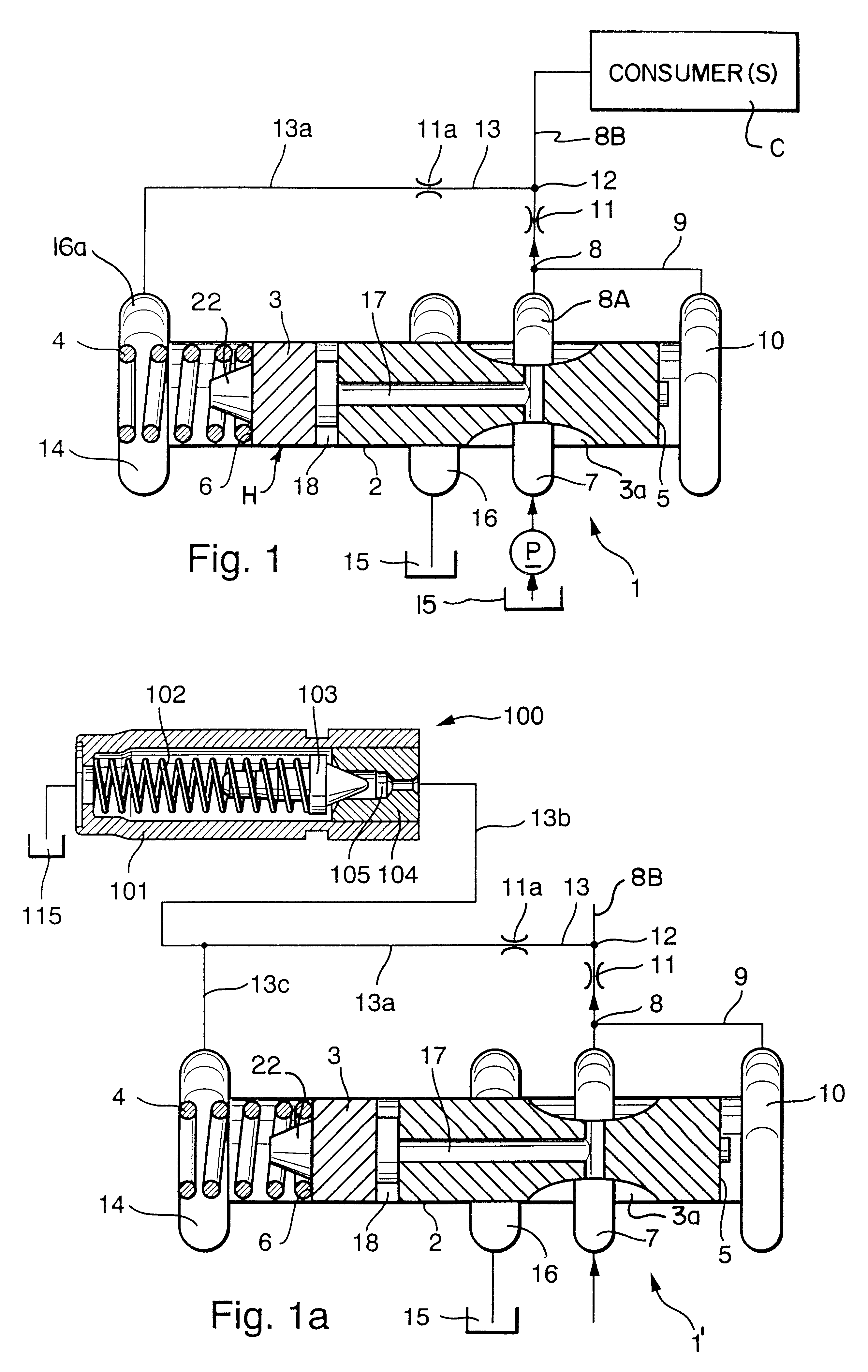
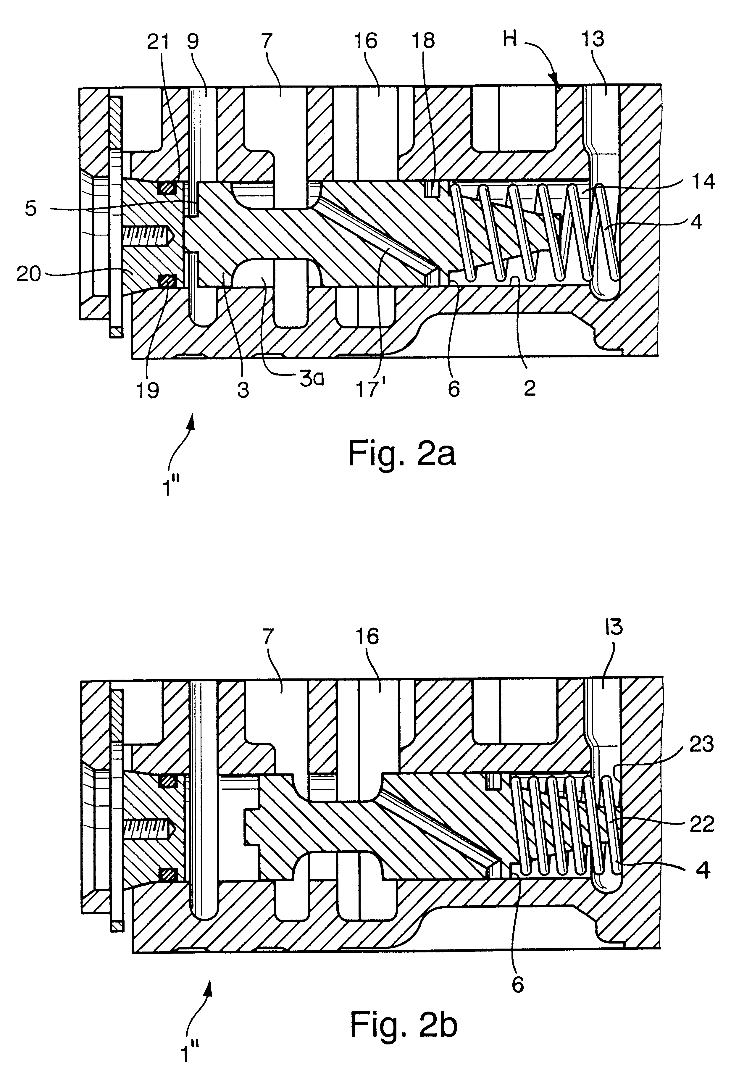
FIG. 1 shows certain relevant details of a regulating valve 1 which embodies one form of the present invention. The valve has a housing or body H which defines an elongated passage 2 (such as a cylindrical bore or hole) for a reciprocable valving element 3, such as a piston and hereinafter called piston. The left-hand end portion of the piston 3 has an end face 6 and defines with the housing H a first chamber 14 forming part of the passage 2 and containing a supply of hydraulic fluid (such as oil) at a first pressure (pilot pressure).

The chamber 14 contains energy storing means 4 serving to bias the piston 3 axially in a direction to the right, as viewed in FIG. 1, namely in a direction to reduce the volume of a second chamber 10 defined by the housing H and the end face 5 of the piston. The illustrated energy storing means 4 is a single cylindrical coil spring reacting against the housing H and bearing upon the end face 6 of the piston 3; the bias of this spring is assisted by pilo...


PUM


Abstract

A valve for regulating the rate of flow and/or the pressure of oil flowing to a transmission or another consumer in the power train of a motor vehicle has a piston which defines with the valve housing a chamber for one or more springs and for oil being admitted through a first inlet by way of a first conduit containing a first throttle. A second inlet admits pressurized oil from a pump, and such oil can be admitted into the consumer by way of a first outlet and a second conduit containing a second throttle and supplying oil to the first conduit. A second outlet can deliver oil from the second inlet to the sump in response to shifting of the piston. A hydraulic seal is established between the piston and the housing intermediate the chamber and the second outlet to prevent leakage of oil from the chamber into the second outlet. Oil leaking from the chamber could adversely influence the characteristics of oil flowing into the consumer.

Description

The present invention relates to valves in general, and more particularly to improvements in fluid flow regulating valves (especially volumetric fluid flow regulating valves). The invention also relates to improvements in methods of regulating the flow of fluids, for example, to the fluid-consuming or fluid-operated components of power trains in motor vehicles.A continuously variable transmission (CVT) of the type often utilized in the power trains of motor vehicles normally comprises several fluid-operated components, e.g., hydraulic cylinder and piston units for the adjustable flanges of pulleys, for torque sensors, for lubricating devices and / or others. Reference may be had, for example, to commonly owned U.S. Pat. No. 5,711,730 granted Jan. 27, 1998 to Oswald Friedmann et al. for "TORQUE MONITORING APPARATUS".Volumetric fluid flow regulating valves (hereinafter called flow regulating or flow control valves for short) are utilized when the flow of a working fluid (e.g., oil) to a...

Claims


Application Information

Patent Timeline
IPC IPC(8): F16H61/662F16H61/66G05D7/01G05D7/00F16K17/04F16H9/00F16K17/22
CPCF16H61/662G05D7/0126Y10T137/0379Y10T137/2579Y10T137/2589Y10T137/2632Y10T137/2635
Inventor FAUST, HARTMUTKEMMNER, BENJAMINEBINGER, GUNTERPANTHER, URBANHOMM, MANFRED
Owner LUK GETRIEBE SYST
Why Eureka
Try Eureka