Device for determining rotational number of DC motors

a technology of dc motor and rotational number, which is applied in the direction of dynamo-electric converter control, instruments, roofs, etc., can solve the problems of cumbersome provision of compensating means and limited frequency range of ripple components of current which the low-pass filter can trea

Inactive Publication Date: 2001-01-09
AISIN SEIKI KK
View PDF6 Cites 15 Cited by
  • Summary
  • Abstract
  • Description
  • Claims
  • Application Information

AI Technical Summary

Problems solved by technology

The frequency range of the ripple component of the current which the low-pass filter can treat is limited, which necessitates the provision of a compensating means to make the signal cor

Method used


Image

  • Device for determining rotational number of DC motors
  • Device for determining rotational number of DC motors
  • Device for determining rotational number of DC motors

Examples


Embodiment Construction

Preferred embodiments of the present invention will be described hereinafter in detail with reference to the accompanying drawings.

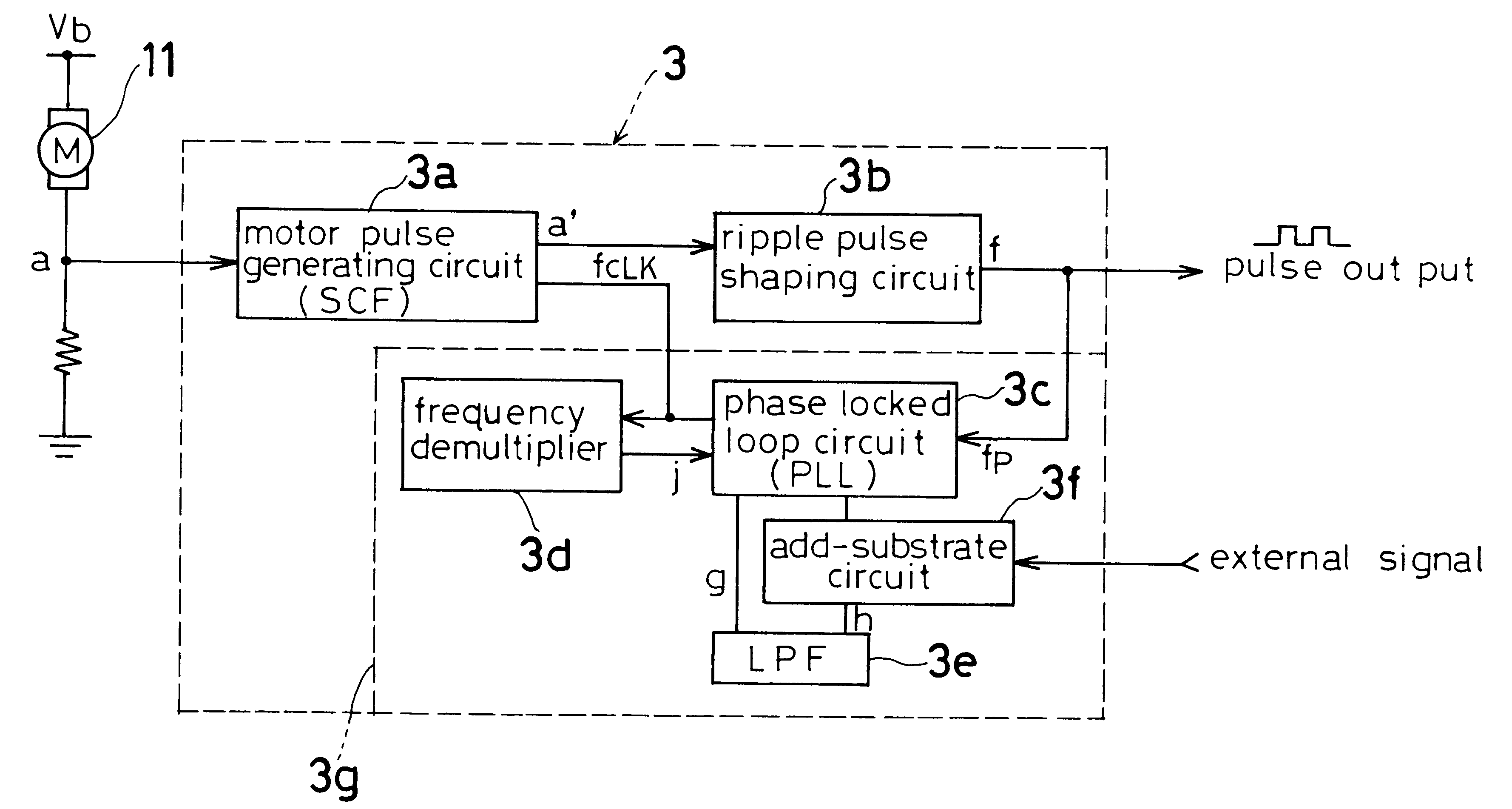
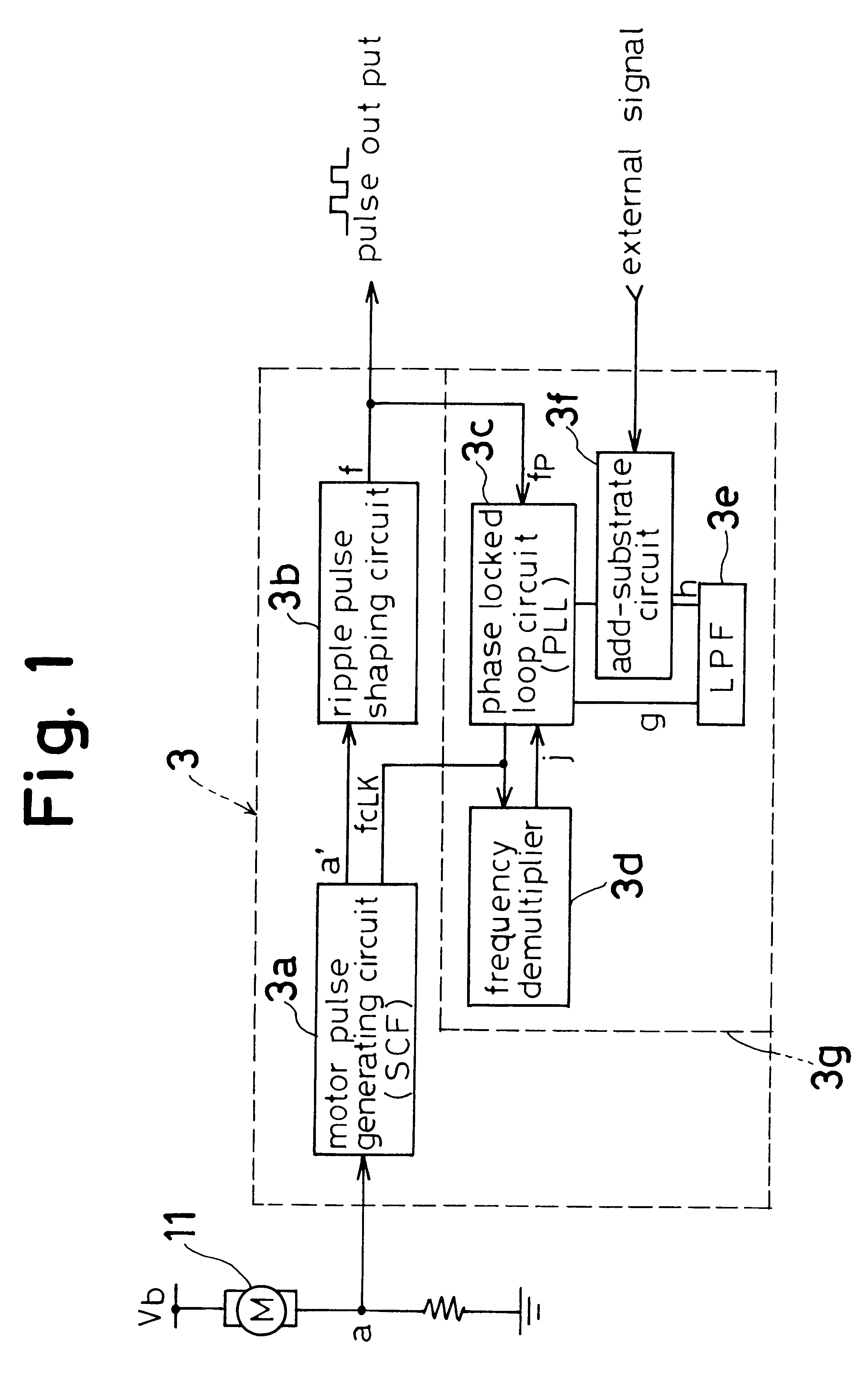
First of all, with reference to FIG. 1, there is illustrated a motor pulse generating circuit 3 which generates a ripple pulse signal whose number of pulses per unit time duration varies with the rotational number of a DC motor 11. The motor pulse generating circuit 3 includes a switched capacitance filter (hereinafter called simply SCF) 3a, a ripple pulse shaping circuit 3b, and a pulse generating circuit 3g. The pulse generating circuit 3g has a phase locked loop circuit (hereinafter called simply PLL) 3c, a frequency demultiplier 3d, a low pass filter (hereinafter simply LPF) 3e, and an add-substrate circuit 3f.

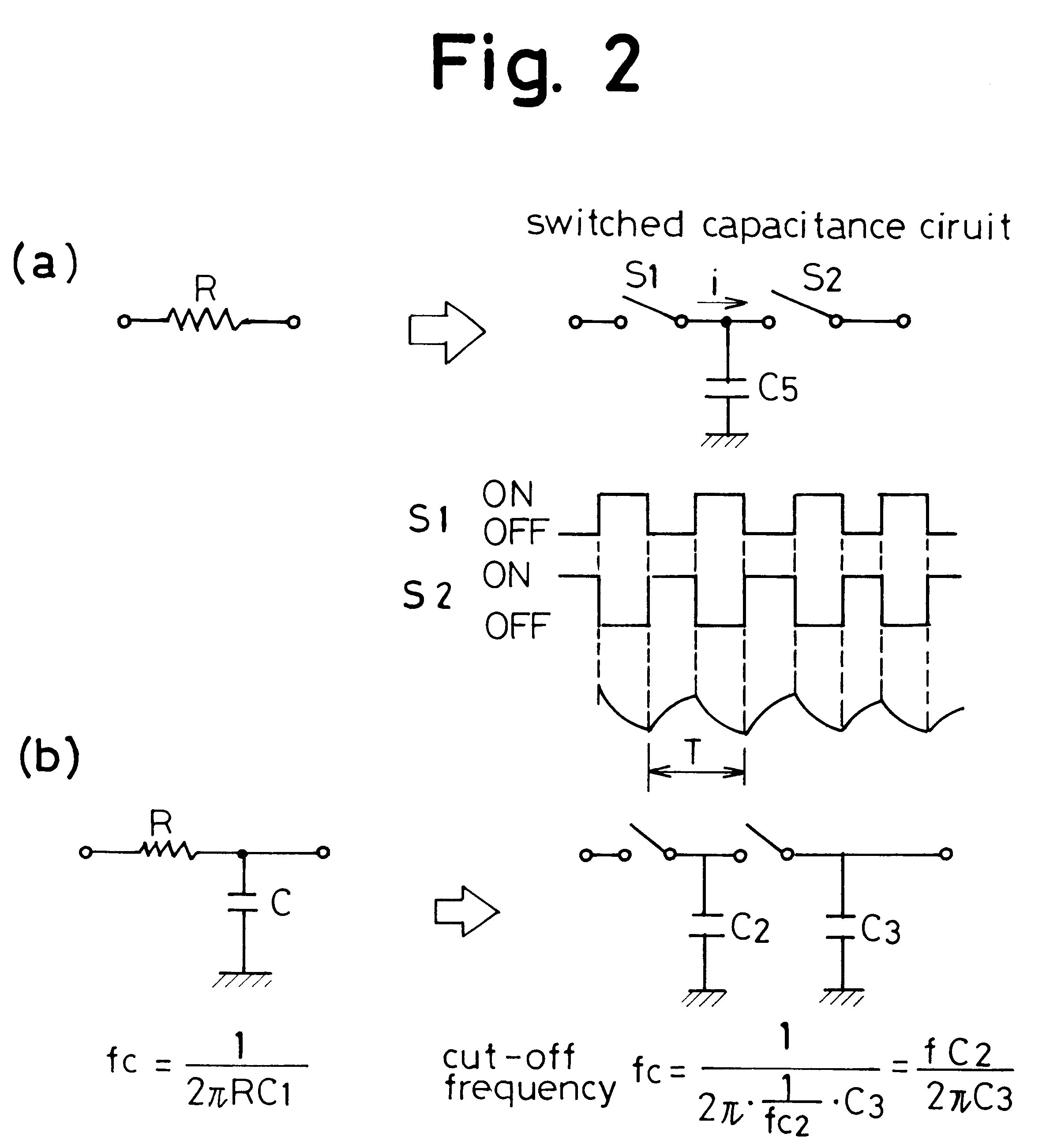
As can be understood easily from FIG. 2, the switched capacitance filter 3a is an application version of a well-known switched capacitance circuit which is constituted by a pair of analogue switches S1 and S2 and a capacitor C5. If the switches...


PUM


Abstract

A device for determining a rotational number of an electric dc motor which drives a moving body of an automobile accessory such a sunroof, or a glass pane of a power window includes a switched capacitance filter for eliminating noise from the motor, a cutoff frequency of the switched capacitance filter being dependent on a clock input thereof; a pulse shaping circuit for generating a ripple pulse signal indicative of the rotational number of the motor by wave-shaping an output of the switched capacitance filter; and a pulse generating circuit providing an output pulse signal so as to establish a condition wherein the frequency of the ripple pulse signal is equalized to the cutoff frequency of the a switched capacitance filter.

Description

1. Field of the InventionThe present invention is directed to a device for determining the rotational number of a dc motor which is used particularly for driving a moving body of an automobile accessory such as a sunroof, a pane of glass in a power window, or an electrically operated seat device.2. Description of Related ArtA conventional device of the kind is disclosed in the U.S. Pat. No. 5,497,326 granted to Berland et al. In this patent, the device issues a signal indicative of the amount of motor rotation. The signal is in the form of a pulse signal, which is generated in such a manner that a ripple component of a current flowing through the motor is formed into a pulse mode by being passed through a circuit including a low-pass filter and other components.The frequency range of the ripple component of the current which the low-pass filter can treat is limited, which necessitates the provision of a compensating means to make the signal correct even though the range of the frequ...

Claims


Application Information

Patent Timeline
IPC IPC(8): B60J7/057B60J7/04G01P3/42G01P3/483G01P3/48B60J1/00B60J1/17H03L7/00
CPCB60J7/0573G01P3/48G01P3/483Y10S388/911
Inventor OKA, TOSHIMITSUAOKI, KOJIKANIE, HIDEYUKIISHIKAWA, HITOSHI
Owner AISIN SEIKI KK
Why Eureka
Try Eureka