Linear-array real-time imaging pulse laser radar device

A real-time imaging, pulsed laser technology, applied in measurement devices, radio wave measurement systems, instruments, etc., can solve the high and low temperature environment and background light environment of linear array lidar. Miniaturization and low power consumption, etc., to achieve the effect of good adaptability to high and low temperature and background light environment, low power consumption, and high temperature stability

Active Publication Date: 2017-05-17
NANJING UNIV OF SCI & TECH
View PDF4 Cites 9 Cited by
  • Summary
  • Abstract
  • Description
  • Claims
  • Application Information

AI Technical Summary

Problems solved by technology

This implementation method adopts flood lighting technology, considering that the sensitive element of the linear array APD detector has a certain duty cycle, which makes the utilization rate of the emitted laser energy low, it is difficult to achieve a large field of view, and it is not conducive to small and low power design
Different sensitive elements in the linear APD detector have different avalanche points, which change with changes in ambient temperature and background light. Therefore, reliable control of the working point of the linear APD detector array is required, which has not been described in the prior art , which leads to the poor adaptability of the linear array lidar to the high and low temperature environment and the background light environment
In terms of signal processing, the existing technology uses high-precision timing circuits or time-to-digital conversion (TDC) circuits, and does not address the preprocessing of ranging echo signals, making it difficult for linear array laser radars to operate under low signal-to-noise ratio conditions. Achieve high accuracy in distance measurement

Method used


Image

  • Linear-array real-time imaging pulse laser radar device

Examples


Embodiment Construction

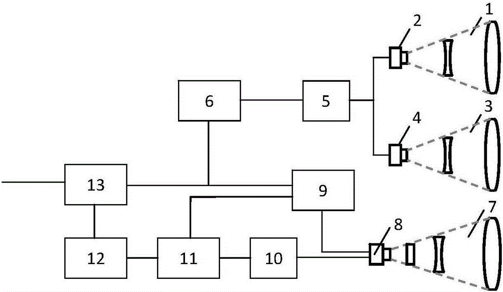
[0013] combine figure 1 , a line array real-time imaging pulse laser radar device of the present invention, comprising a first optical transmitting antenna 1, a first N-element laser diode array 2, a second optical transmitting antenna 3, a second N-element laser diode array 4, a narrow pulse Laser drive circuit 5, timing control circuit 6, optical receiving antenna 7, 2N+1 element APD detector array 8, bias high voltage automatic control circuit 9, 2N+1 parallel preamplifier circuit 10, 2N+1 parallel pulse Shaping circuit 11, 2N channels of binary signal parallel preprocessing circuit 12 and 2N channels of parallel high-precision time-to-digital conversion circuit 13, the optical axes of the first optical transmitting antenna 1 and the second optical transmitting antenna 3 are parallel, and the focal planes are respectively set The first N-element laser diode array 2 and the second N-element laser diode array 4, the centers of the first N-element laser diode array 2 and the s...


PUM


Abstract

The invention discloses a linear-array real-time imaging pulse laser radar device. The device comprises 2 optical emission antennas, 2 N-element laser diode arrays, a narrow pulse laser driving circuit, a sequential control circuit, an optical receiving antenna, a 2N+1 element APD detector array, a bias high-voltage automatic control circuit, 2N+1 paths of parallel preposition amplification circuits, 2N+1 paths of parallel pulse shaping circuits, 2N paths of binary signal parallel processing circuits and 2N paths of parallel high-precision time-digital conversion circuits. In the invention, a laser diode array is combined with field splicing illumination, a linear array APD detector receiving, constant false alarm automatic gain control and real-time parallel signal pretreatment so that large field and high spatial resolution imaging can be realized. Advantages of miniaturization, low power consumption and the like are possessed. Under a low signal to noise ratio condition, high accurate measurement and real-time range finding can be performed. And the device can be used in fields of low air-to-ground three-dimensional imaging, vehicle-mounted three-dimensional scene acquisition and the like.

Description

technical field [0001] The invention relates to a laser radar device, in particular to a linear array real-time imaging pulse laser radar device. Background technique [0002] With the development of laser technology, lidar technology has developed from single-point rapid scanning detection imaging to linear array real-time imaging. Real-time linear array imaging can greatly increase the frame rate of distance imaging, and has broad application prospects in many fields such as surveying and mapping, industrial production, military reconnaissance, and aerospace. [0003] The existing linear array lidar technology using the pulse time-of-flight ranging principle usually shapes the laser beam output by the laser into a strip-shaped laser emission, and then receives the laser echo by the linear array APD detector, and the laser output from the APD detector After the echo electrical signal is amplified and shaped, it is used as a timing stop signal to control the timing circuit ...

Claims


Application Information

Patent Timeline
Patent Type & Authority Applications(China)
IPC IPC(8): G01S17/89
CPCG01S17/89
Inventor 李振华来建成王春勇严伟纪运景黄宏坤
Owner NANJING UNIV OF SCI & TECH
Why Eureka
Try Eureka