
Ferritic heat resistant steels

a heat-resistant steel and ferritic technology, applied in the field of ferritic heat-resistant steels, can solve the problems of reducing the reduction area of creep rupture, requiring a great deal of experimental work, and requiring a great deal of labor, time and cost for the development of new steels, such as the steels in figs. 1 and 2

Inactive Publication Date: 2001-01-16
THE KANSAI ELECTRIC POWER CO
View PDF12 Cites 18 Cited by
  • Summary
  • Abstract
  • Description
  • Claims
  • Application Information

AI Technical Summary

Benefits of technology

(4) A ferritic heat resistant steel characterized by consisting of, in mass a basis, 0.07-0.14% carbon, 0.01-0.10% nitrogen, not more than 0.10% silicon, 0.12-0.22% vanadium, 10.0-13.5% chromium, not more than 0.45% manganese, 0.5-4.3% cobalt, 0.02-0.10% niobium, 0.02-0.8% molybdenum, 0.5-2.6% tungsten, 0-0.02% boron, 0-3.0% rhenium and the balance iron and incidental impurities.
(5) A ferritic heat resistant steel characterized by consisting of, in mass % basis, 0.02-0.12% carbon, 0.01-0.10% nitrogen, not more than 0.50% silicon, 0.15-0.25% vanadium, 9.0-13.5% chromium, n...

Problems solved by technology

However, addition of more than 1% copper to a steel decreases its reduction of area upon creep rupture.
However, a great deal of experimental work will be required before obtaining a novel sort of steel with desirable chemical and physical properties.
Development of new steels like the steels in FIGS. 1 and 2 in accordance with the conventional trial-and-error method requires a great deal of labor, time and cost.
However, it has not been certain that the novel alloy designing system can be applicable to produce ferritic heat resistant steels.

Method used


Image

  • Ferritic heat resistant steels
  • Ferritic heat resistant steels
  • Ferritic heat resistant steels

Examples


example

1. Preparation of Test Specimens

(1) T-series Steel Specimens

Six steels having different compositions as shown in FIG. 14 were melted in a high frequency vacuum induction furnace and cast into six ingots each having a weight of 50 kg. Each ingot was heated to a temperature of 1170.degree. C., hot forged into a billet having a 130 mm thickness and a 35 mm width. The obtained billet was normalized by keeping it at 1100.degree. C. for 5 hours and then air cooled, followed by an annealing treatment wherein the billet was kept at 720.degree. C. for 20 hours and then air cooled.

After that, the following heat treatment steps simulate the heat cycle suffered by the center zone of an actual turbine rotor.

(1) keeping at 1070.degree. C. for 5 hours and oil quenching (hardening)

(2) keeping at 570.degree. C. for 20 hours and air cooling (first tempering)

(3) keeping at T.degree. C. for 20 hours and air cooling (secondary tempering)

Specimen "TO" is the aforesaid conventional heat resistant turbine ...


PUM

PropertyMeasurementUnit
Fractionaaaaaaaaaa
Fractionaaaaaaaaaa
Fractionaaaaaaaaaa

Abstract

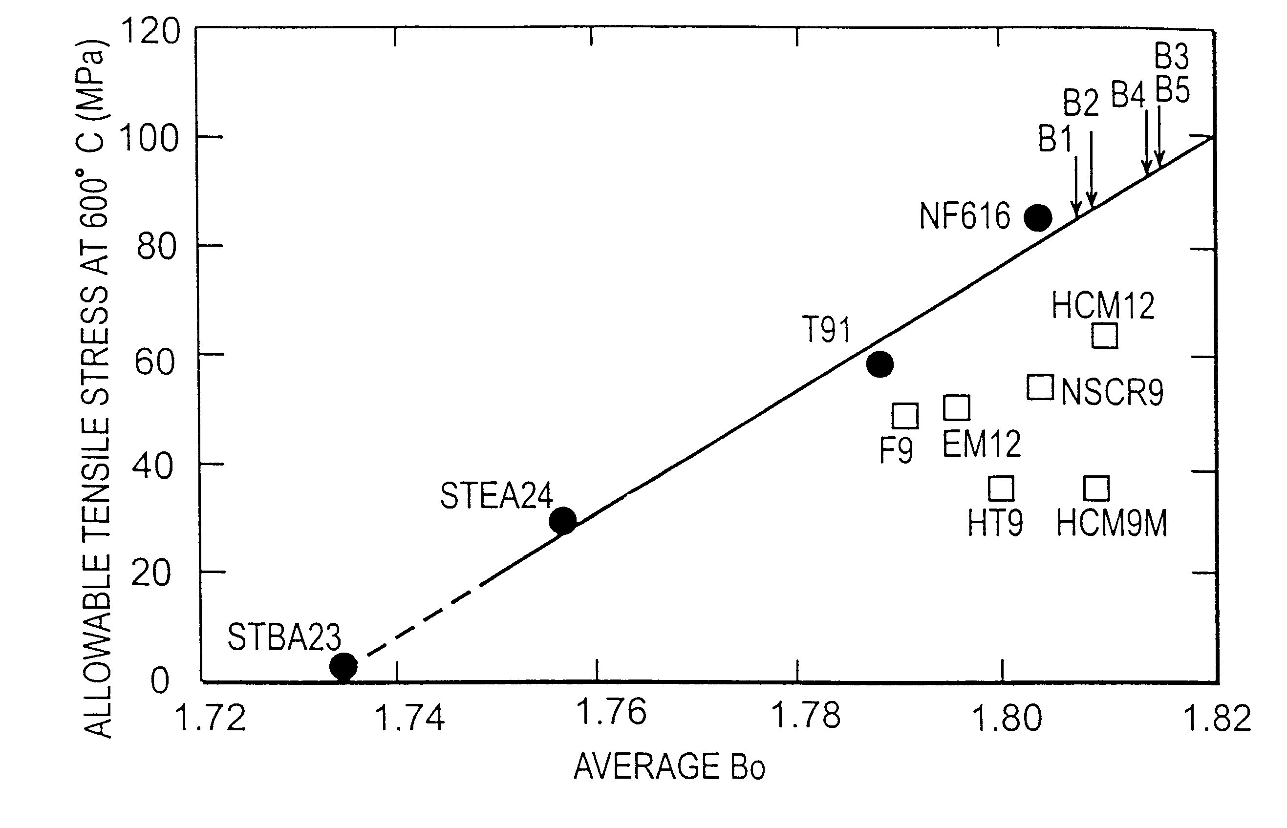
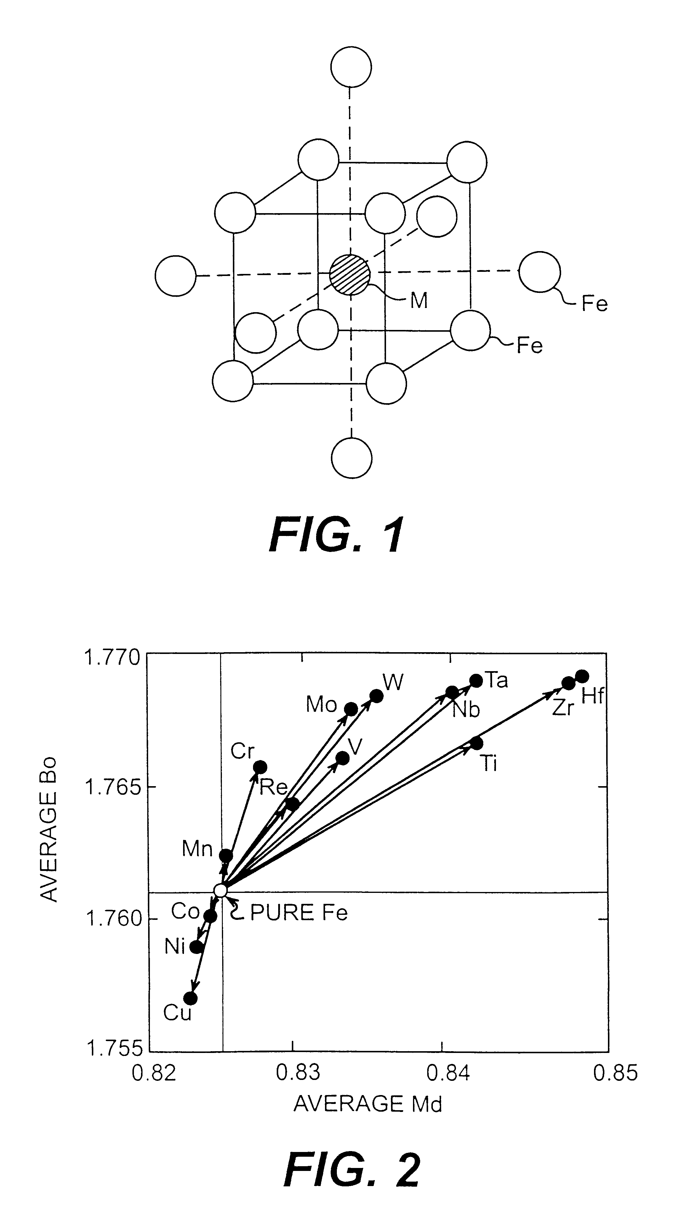
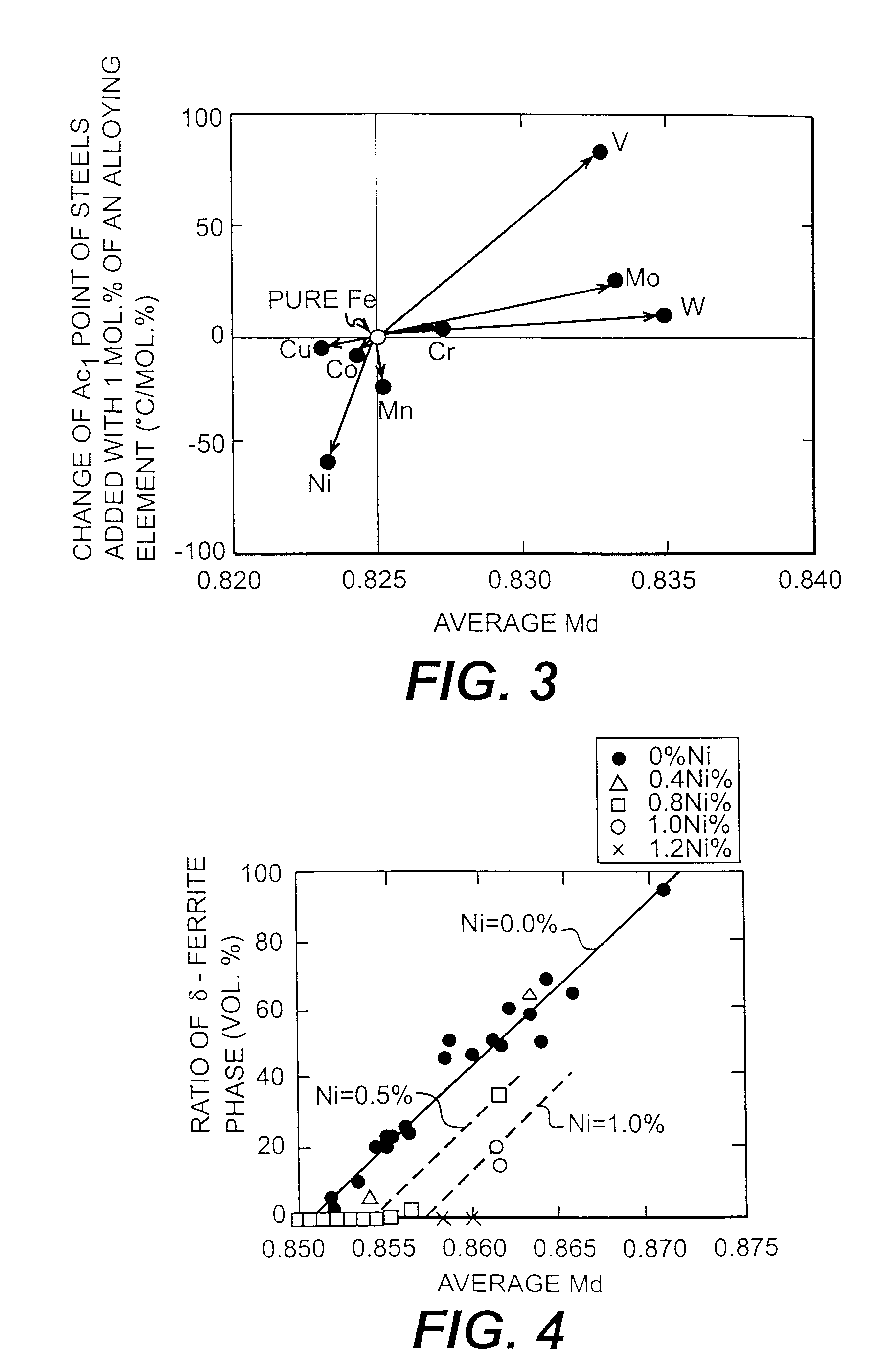
A method of designing a ferritic iron-base alloy having excellent characteristics according not to the conventional trial-and-error technique but to a theoretical method, and a ferritic heat-resistant steel for use as the material of turbines and boilers usable even in an ultrasupercritical pressure power plant. Specifically, the d-electron orbital energy level (Md) and the bond order (Bo) with respect to iron (Fe) of each alloying element of a body-centered cubic iron-base alloy are determined by the Dv-Xalpha cluster method, and the type and quantity of each element to be added to the alloy are determined in such a manner that the average Bo value and average Md value represented respectively by the following equations:coincide with particular values conforming to the characteristics required of the alloy; wherein Xi represents atomic fraction of an alloying element i, and (Bo)i and (Md)i represent respectively the Bo value and Md value of the element i. Preferably, the average Bo value and average Md value are, respectively, in the ranges of 1.805 to 1.817 and 0.8520 to 0.8628.

Description

This invention relates to a method of designing ferritic iron-base alloys on the basis of a predicting system without depending upon conventional trial-and-error experimental procedures. This invention also relates to high strength ferritic heat resistant steels which exhibit high temperature strength and other physical and chemical properties more excellent than those of the conventional ferritic heat resistant steels. The steels are particularly suitable for materials of turbines and boilers.Although heat resistant steels are used in various areas, materials of turbines and boilers are the typical uses of the ferritic heat resistant steels. Therefore, the heat resistant steels of this invention will be specified in terms of turbine and boiler materials hereinafter.Most of conventional heat resistant steels hitherto developed for use in boiler and turbine materials contained 9 to 12% chromium as well as one or more of carbon, silicon, manganese, nickel, molybdenum, tungsten, vanadi...

Claims


Application Information

Patent Timeline
IPC IPC(8): C22C38/00C22C38/36C22C38/26C22C38/22C22C38/54
CPCC22C38/00C22C38/001C22C38/22C22C38/26C22C38/36C22C38/54
Inventor MORINAGA, MASAHIKOMURATA, YOSHINORIHASHIZUME, RYOKICHI
Owner THE KANSAI ELECTRIC POWER CO
Learn More