Cesium formate drilling fluid recovery process

a technology of drilling fluid and csf, which is applied in the direction of separation process, membrane, borehole/well accessories, etc., can solve the problems of inability to afford wells, limited quantity of csf drilling fluid, and high price of lubricants

Inactive Publication Date: 2001-01-23
HUTCHISON HAYS SEPARATORS
View PDF7 Cites 70 Cited by
  • Summary
  • Abstract
  • Description
  • Claims
  • Application Information

AI Technical Summary

Problems solved by technology

In addition, the drilling fluids used in this process often recover and carry a stream of ground particles.
These have the form of lubricants which are more expensive, with prices approaching $300 per barrel.
Otherwise, it can not be afforded in wells where its use is normally indicated.
Moreover, CsF drilling fluid is manufactured and marketed in a limited quantity because of the difficulties of manufacture and the lack of feed stock for making CsF drilling fluid.
An overbalance situation occurs when the drill bit enters a formation where high pressure is likely to be encountered.
It is especially not desirable when drilling into formations which are likely to start producing flowing hydrocarbons.
Moreover, when the hole is deviated towards the horizontal, it then requires that the pipe snake around the corner, so to speak, and that creates great difficulties in applying torque to the pipe string from the rotary table.
This can easily create a catastrophic blowout because the aggregate pressure at the bottom become less and less over time, and a run away condition may be encountered in which formation fluids flow freely into the well borehole.
Such a fluid is relatively expensive, having a cost of about $4,000 per barrel in 1998 prices.
This expensive and highly desirable drilling fluid is used in a well and then must be recovered.
In effect, this would mean that a well requiring 1,000 barrels of drilling fluid would involve a capital expense of approximately $4 million for drilling fluid to finish the drilling process and would recover only about two thirds of that value.
Even should the recovery be raised to 75%, meaning approximately $3 million worth of drilling fluid, that would still represent a significant cost.
It runs the risk of picking up cuttings and other debris during drilling.
It is a filter surface which runs the risk of blinding.
However, that makes the controller somewhat more complicated.
In the instance where a cesium formate well fluid system is used, a great portion of it is lost to the drilling process.
It is not easy to clean up this fluid.
Merely treating the CsF drilling fluid with individual stages of centrifugal separation or membrane separation usually will not recover enough of the CsF.
Likewise, processing the CsF spent fluid through a wash tank is usually inadequate.
The loss, however, is excessive.
Even by adding the feedback loop, the rate of recovery, while good, is not high enough.

Method used


Image

  • Cesium formate drilling fluid recovery process
  • Cesium formate drilling fluid recovery process
  • Cesium formate drilling fluid recovery process

Examples


Embodiment Construction

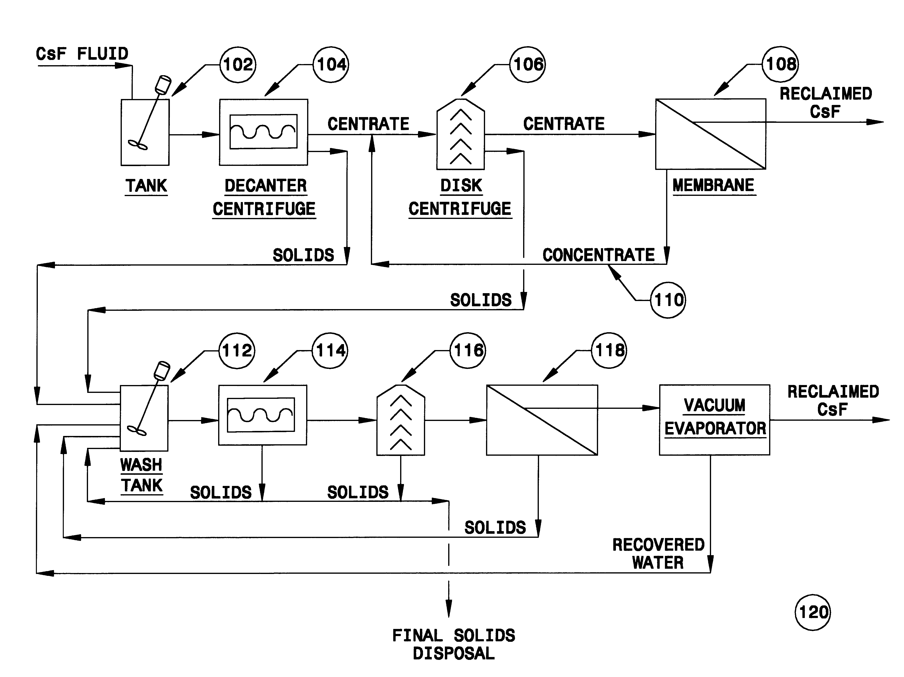
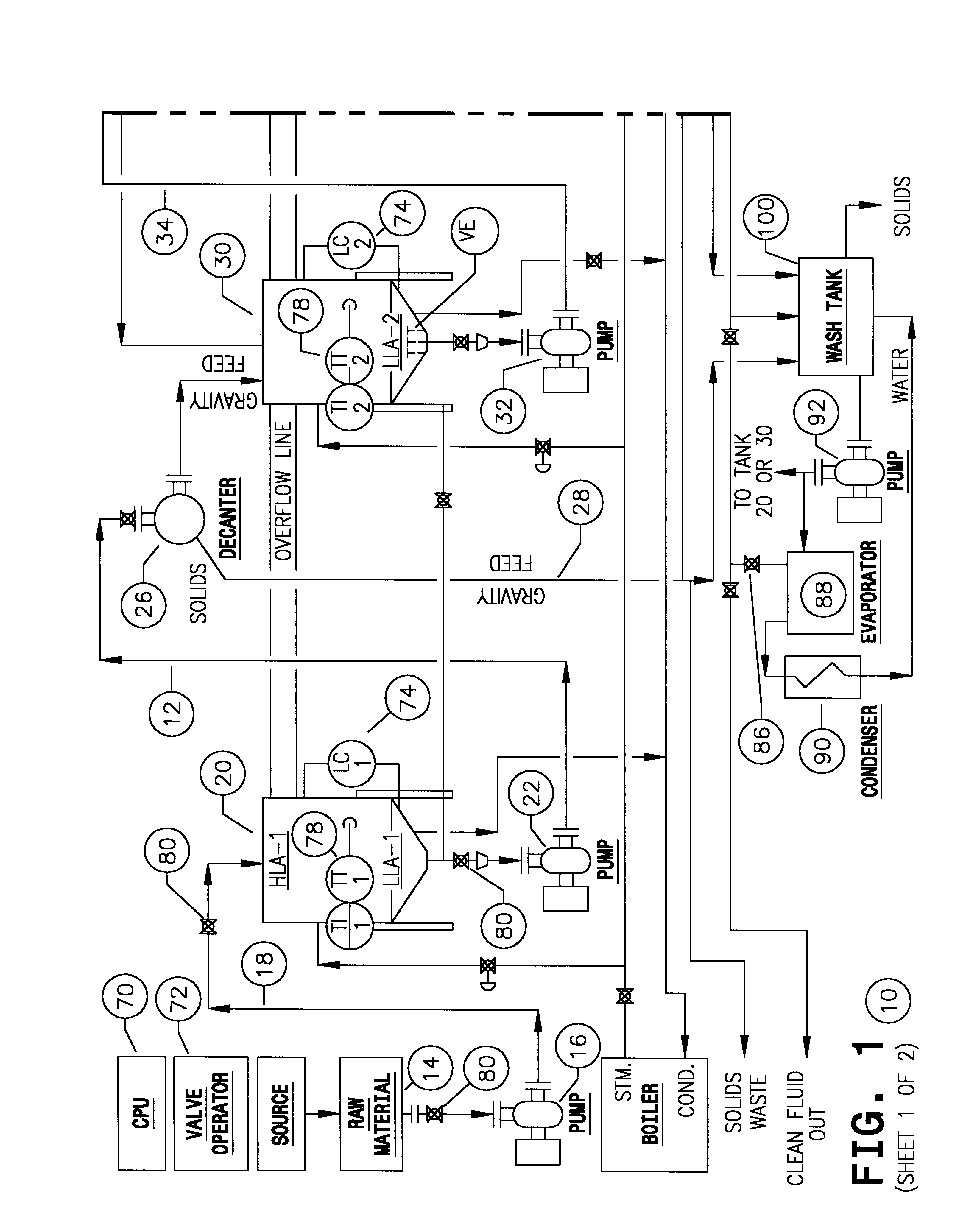
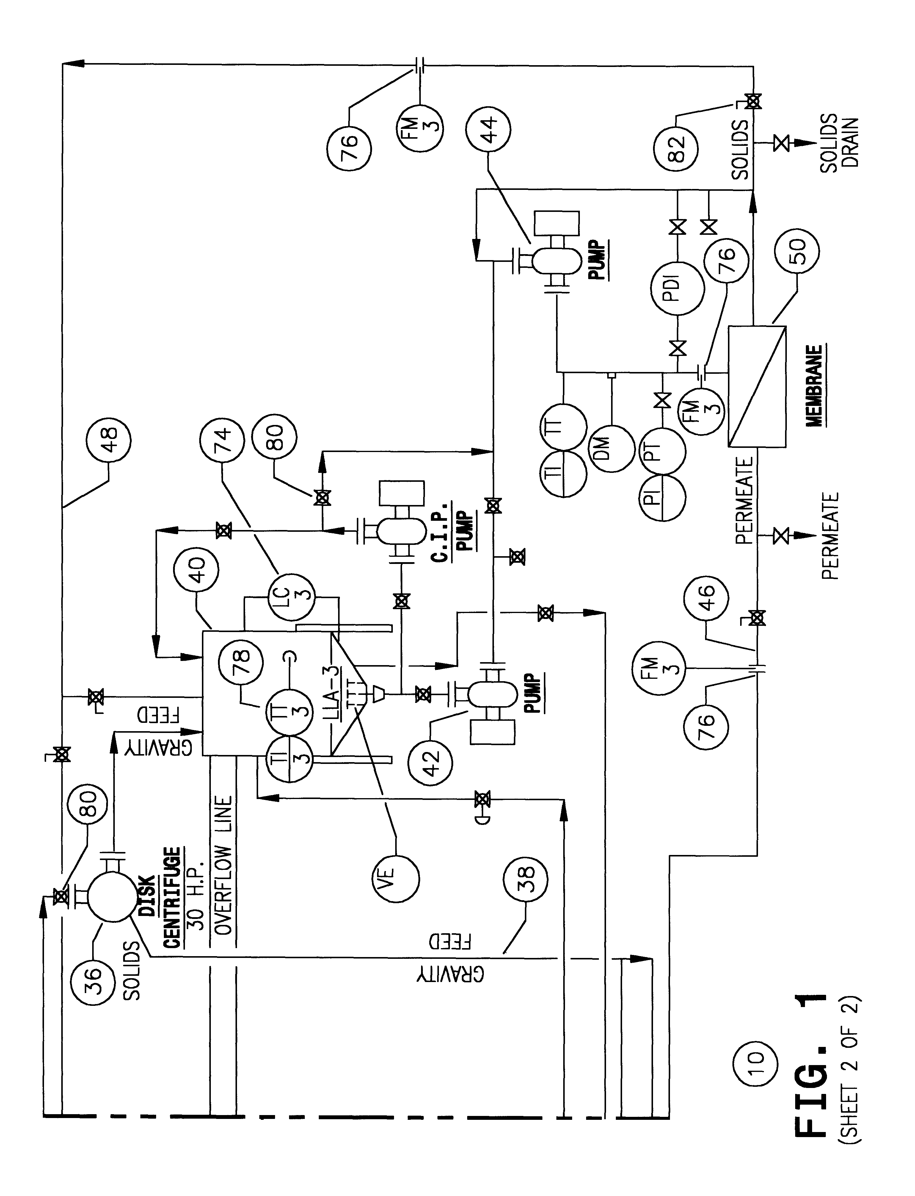
FIG. 6 shows a CsF stream which is input to the system 120. As before, this system incorporates an input tank 102, a decanter centrifuge 104 and a disc centrifuge 106. These are output to a membrane separator 108. There is a feedback pathway 110 which enables the output of the CsF fluid. In this particular instance, and without any further assistance, the output ratio again will be at least about 65%, and can be as high as about 70% or even 75%. The system illustrated in the top part of FIG. 6 can be precisely the same equipment shown in FIG. 1; FIG. 6 assists in an understanding in large part because it omits the complexities of tanks and pumps, control valves, and the like; it simply shows the pathway of the fluid flow through the three stages of separation and incorporates the feedback loop 110 consistent with the construction of the system 10, see FIG. 1.

The solids from the first and second centrifuges are discharged to the wash tank 112. In addition, it incorporates the centrif...


PUM

PropertyMeasurementUnit
sizeaaaaaaaaaa
pore diameteraaaaaaaaaa

Abstract

This disclosure sets out a method and apparatus for recovery of cesium formate in water solution after use in a drilling process where trash and other debris accumulate in the drilling fluid. It incorporates a first stage centrifuge, a second stage centrifuge and a membrane separator serially connected, and incorporates a feedback loop. A feedback loop iteratively redirects solids and heavy weight concentrate after processing and recycles it to enhance recovery by enhanced removal of cuttings and trash in the stream. In addition, cuttings and other solids removed from the fluid stream are introduced into a wash tank, mixed with water, and the cuttings are further processed to remove remnants of the cesium formate. These recovered cesium formate remnants are passed through an evaporator to regain the density loss attributable to the dilutive wash water. The cuttings can then be thrown away without throwing away the valuable cesium formate in the drilling solution.

Description

BACKGROUND OF THE DISCLOSUREThe present disclosure is directed to a method of recovery and the related apparatus for use in recovery of drilling, drill-in and completion fluids used in exploration for hydrocarbons. More specifically, this is concerned with recovery of expensive drilling, drill-in and completion fluids, and especially those which utilize cesium formate as the base fluid. Before discussing that particular fluid, the context of drilling, drill-in and completion fluids use (definitions given below) and recovery should be set forth. Within this document, cesium formate base fluid used in the exploration for hydrocarbons will be often referred to as "drilling fluid".While it is possible to drill for oil and gas formations using air as drilling fluid, the most common process involves drilling with drilling mud. Drilling mud is routinely a mixture of water and barite. Various and sundry clay constituents may be added to impart added weight to the water, and to provide the d...

Claims


Application Information

Patent Timeline
Patent Type & Authority Patents(United States)
IPC IPC(8): B01D71/00B01D63/06B01D61/14B01D71/02C08B30/00C08B30/04E21B21/06E21B21/00
CPCB01D61/14B01D61/145B01D61/147B01D63/063B01D67/0041B01D69/12B01D71/024C08B30/04E21B21/06B01D69/04B01D2325/02B01D2325/022
Inventor POTTER, J. LEONHENSLEY, GART L.
Owner HUTCHISON HAYS SEPARATORS
Why Eureka
Try Eureka