
Spontaneous firing explosive composition for use in a gas generator for an airbag

a technology of explosive composition and gas generator, which is applied in the direction of explosives, other chemical processes, furnaces, etc., can solve the problems of increasing the size of gas generator, increasing the cost of gas generator, so as to prevent the housing from exploding and ensure the safety of the gas generator. , the effect of preventing the explosion

Inactive Publication Date: 2001-01-23
NIPPON KAYAKU CO LTD +1
View PDF11 Cites 38 Cited by
  • Summary
  • Abstract
  • Description
  • Claims
  • Application Information

AI Technical Summary

Benefits of technology

The aforementioned fuel ingredient is a gas-generating ingredient which burns and decomposes in order to produce gas. The oxidizing agent is a ingredient for helping the fuel ingredient to burn. And the combustion catalyst is a ingredient for adjusting the oxidizing reaction and the spontaneous firing temperature. By combining those ingredients, a spontaneous firing enhancer is produced with a high gasification percentage and good fuel-firing property.
These binders offer another advantage as follows. When the explosive composition with the above binders burns, the harmful fine particles produced by combustion, react with the metal oxides produced by the decomposition reaction of the binders, then slugs are formed. The slugs are easily removed by the filter.

Problems solved by technology

However, according to this way, the packing percentage of the gas generating agent pellets decreases and a larger size gas generator is required.
Also, when the packing density of the gas generating agent is raised so as to reduce size and weight of the gas generator, it is difficult for the heated boron to stick to the pellets of the gas generating agent uniformly and it hard to adjust the combustion velocity.
Further, when a car which has met with no accident, is treated to abandon, the gas generator is remove from an air bag module and incinerated since it is difficult to pick up the only gas generating agent from the air bag module.
While the incineration of the gas generator, the housing of the gas generator is heated and becomes so brittle.
In this time, the gas generator may explode and break because of combution of the gas generating agent, which can bring danger to the neighboring area.
Also, this kind of danger may occur in other case than the incineration, for example, when a car catches fire at accident other than a collision.
However, this method has a problem that the fourth material like a spontaneous firing explosive is needed in addition to the gas generating agent, the enhancer and the igniter.
This is one of reasons of increasing a cost for producing the gas generator.

Method used


Image

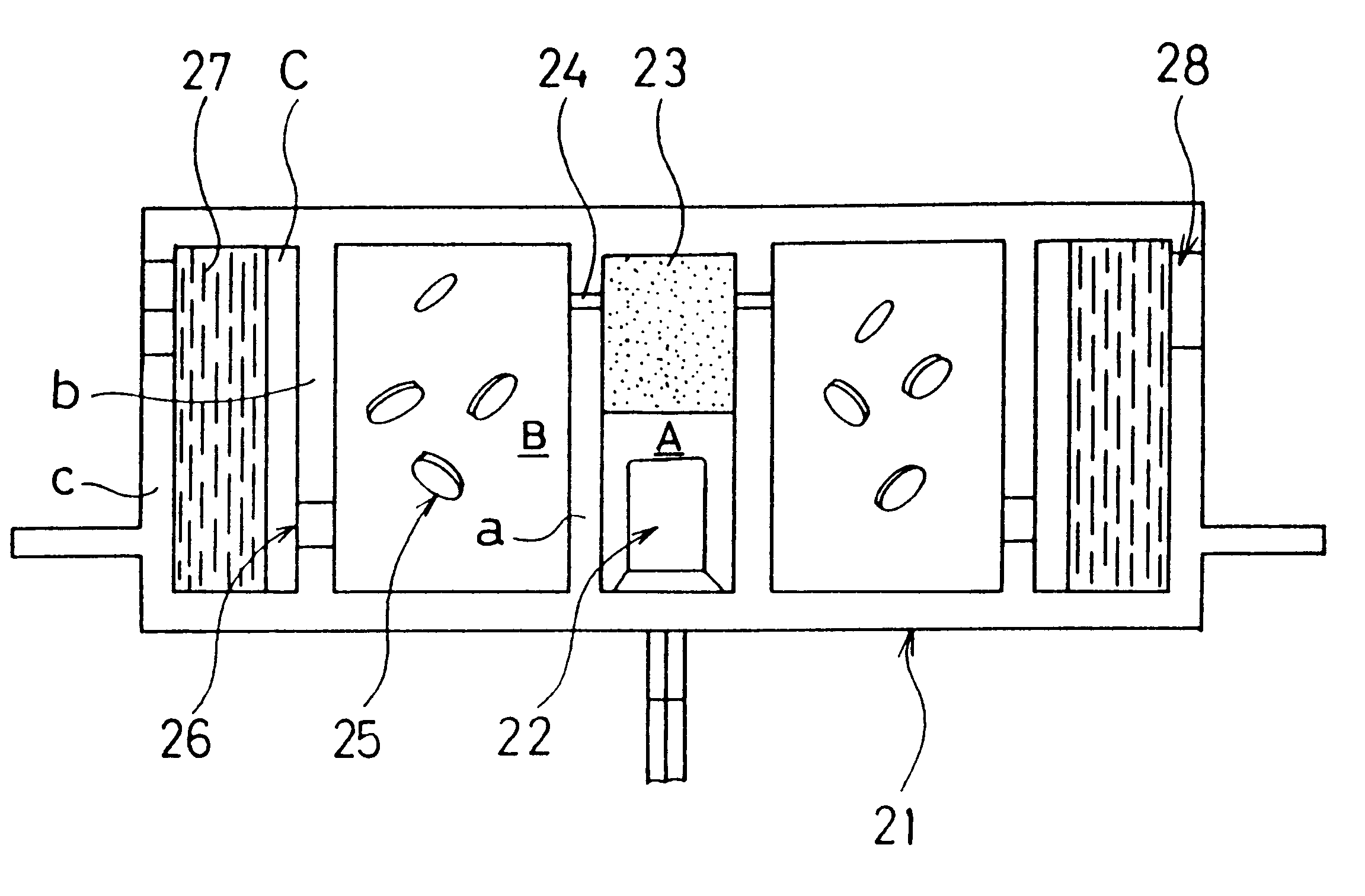
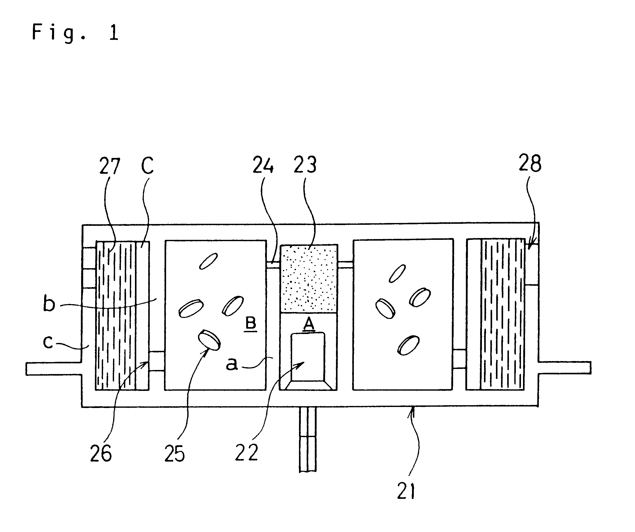
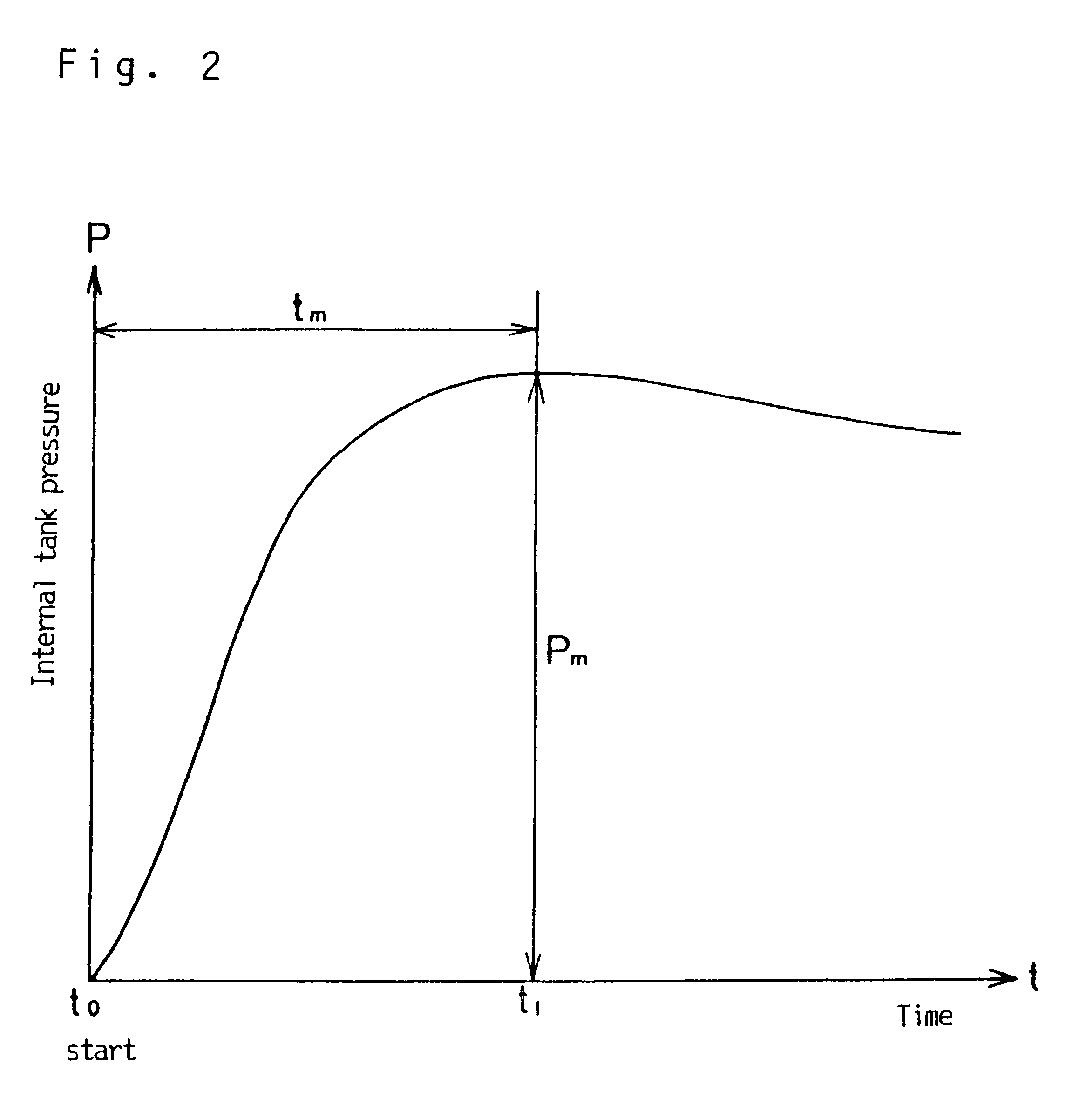
  • Spontaneous firing explosive composition for use in a gas generator for an airbag
  • Spontaneous firing explosive composition for use in a gas generator for an airbag
  • Spontaneous firing explosive composition for use in a gas generator for an airbag

Examples


embodiment 2

[EMBODIMENT 2]

The construction of the gas generator used in the embodiment 2 is illustrated in FIG. 4. In FIG. 4, the reference number 30 indicates a combustion chamber containing pellets of the gas generating agent 36. The reference number 32 shows a firing means mounted in the center of the combustion chamber 30, which comprises a squib 34 and a enhancer 35 for firing the gas generating agent 36.

The reference number 33 is a filter chamber surrounding the combustion chamber annularly, which cools the gas passing through the combustion chamber 30 and collects the slug from the gas. Sparks from the squib 34 melt a container 40b made of aluminum foil then the enhancer 35 ignites. A high-temperature gas generated during the combustion of the enhancer bursts into the combustion chamber 30 to melt a container 41 made of aluminum foil for the gas generating agent in the combustion chamber 30 then fires the gas generating agent 36 in the combustion chamber 30. The gas produced during the c...

embodiment 3

[EMBODIMENT 3]

An embodiment of a gas generator having the construction illustrated in FIG. 6 will now be described. This gas generator in FIG. 6 has structual differences from the gas generator in FIG. 4 as follows. In FIG. 6, an integral-type igniter 32 is employed in which an enhancer 35 is incorporated in the igniter 32. The annular aluminum foil container 41 has a portion which can communicate in the radial direction at its upper side, which is disposed in an annular combustion chamber 30 formed in the space between the igniter 32 and a partition wall 39. The gas generating agent 36 is contained in the container 41. An explosive composition employed as an enhancer and a gas generating agent is the same one as employed in the embodiment 2. Combustion tests using the gas generator of Embodiment 3 were done in the same manner as Embodiment 2. Satisfactory results were obtained as well as in Embodiment 2. Especially, in Embodiment 3, a holder for the enhancer as shown in the prior a...

embodiment 4

[EMBODIMENT 4]

A case in which explosive compositions of the enhancer and the gas generating agent are different from each other, will be described hereinafter.

36.2% by weight of 5-amino-1H-tetrazol (5-ATZ) was prepared as the fuel ingredient to be pulverized into particles of which each diameter was 100 .mu.m or less and a 50% average particle diameter of a reference number was 30 .mu.m. 59.3% by weight of strontium nitrate was prepared as the oxidizing agent to be pulverized into particles of which each diameter was 100 .mu.m or less and a 50% average particle diameter of a reference number was 45 .mu.m. 4.5% by weight of synthetic hydrotalcite was prepared as the binder to be pulverized into particles of which each diameter was 50 .mu.m or less and a 50% average particle diameter of a reference number was 10 .mu.m. These ingredients were mixed well in a V-shaped mixer. In order to obtain pellets of the gas generating agent, the mixture was filled into a reference mold then press-f...


PUM


Abstract

A spontaneous firing explosive composition for use in a gas generator for an airbag containing a fuel, an oxidizer, a combustion modifier, and a binder.

Description

The present invention relates to a gas generating agent and a enhancer for use in a gas generator to inflate an air bag for protection the occupant in a vehicle and a gas generator using aforesaid gas generating agent and enhancer. More specifically, this invention relates to an enhancer which has a spontaneous firing function and is safe-to-handle. And the enhancer is especially excellent in the properties required in the ignition agent for gas generating agents and of which composition is can also be used as gas generating agent itself. Further, this invention relates to a gas generator which is provided with an excellent spontaneous firing function to use aforesaid enhancer of which composition can also be used as gas generating agents.As dissolved by U.S. Pat. No. 4,547,342 and FIG. 11, the gas generator that has been generally used, comprises a housing 1 with an upper container body 2 and a lower container body 3. The upper container body 2 has an inner cylinder wall 4 and an o...

Claims


Application Information

Patent Timeline
IPC IPC(8): C06B23/00C06D5/00C06C9/00C06D5/06B60R21/26B60R21/264C06B45/04C06C7/00
CPCC06B23/007C06C9/00C06D5/06Y10S149/11C06D5/00B60R21/26
Inventor KANDA, TAKESHIYOKOTE, NOBUAKISASO, TAKASHITANAKA, KOJIKUROIWA, AKIHIKOITO, YUJIKIMURA, AYUMU
Owner NIPPON KAYAKU CO LTD
Learn More