Vehicle suspension control with compensation for yaw correcting active brake control

a technology of active brake control and suspension control, which is applied in the direction of shock absorbers, instruments, cycle equipment, etc., can solve the problems of undesirable body movement, unoptimized specific dynamic situation, and undesirable body movement for occupants of vehicles

Inactive Publication Date: 2001-01-30
BWI +1
View PDF19 Cites 48 Cited by
  • Summary
  • Abstract
  • Description
  • Claims
  • Application Information

AI Technical Summary

Benefits of technology

This invention adapts a variable damping suspension to be responsive to a specific active brake signal from a vehicle braking control that is applying a greater braking force to one front corner than the other to affect vehicle yaw rate so as to optimally control pitch at the one front corner and the diagonally opposed rear corner and thus the resulting tilting motion of the vehicle body about a diagonal axis.
More specifically, a vehicle suspension system is responsive to an active brake signal from a brake system indicating the application of a greater braking force to one front corner brake than to the other front corner brake to affect vehicle yaw rate. The vehicle suspension system determines the relative velocities of the front corner suspension adjacent the front corner brake receiving the greater braking force and the diagonally opposed rear corner suspension and further determines a compression damping command for the front corner suspension and a rebound damping command for the rear corner

Problems solved by technology

But the application of a braking force at a specific corner also creates a body pitch motion at that corner that can cause a tilting motion of the vehicle body around a diagonal axis.
Such body movement may be undesirable to occupants of the vehicle.
Such systems are generally responsive to vehicle body motions to reduce the diagonal body tilting motion described above, but such general response requires t

Method used


Image

  • Vehicle suspension control with compensation for yaw correcting active brake control
  • Vehicle suspension control with compensation for yaw correcting active brake control
  • Vehicle suspension control with compensation for yaw correcting active brake control

Examples


Embodiment Construction

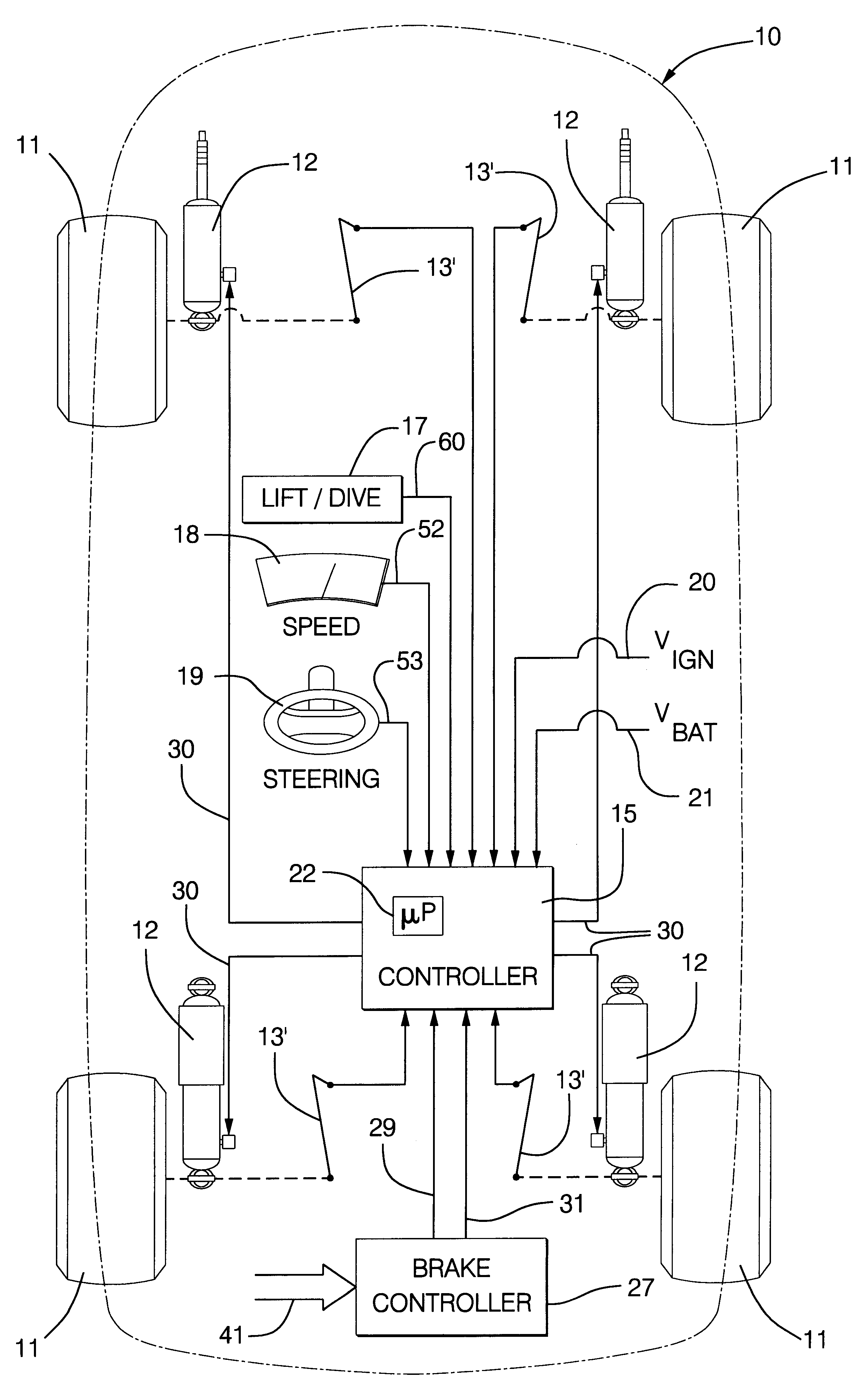
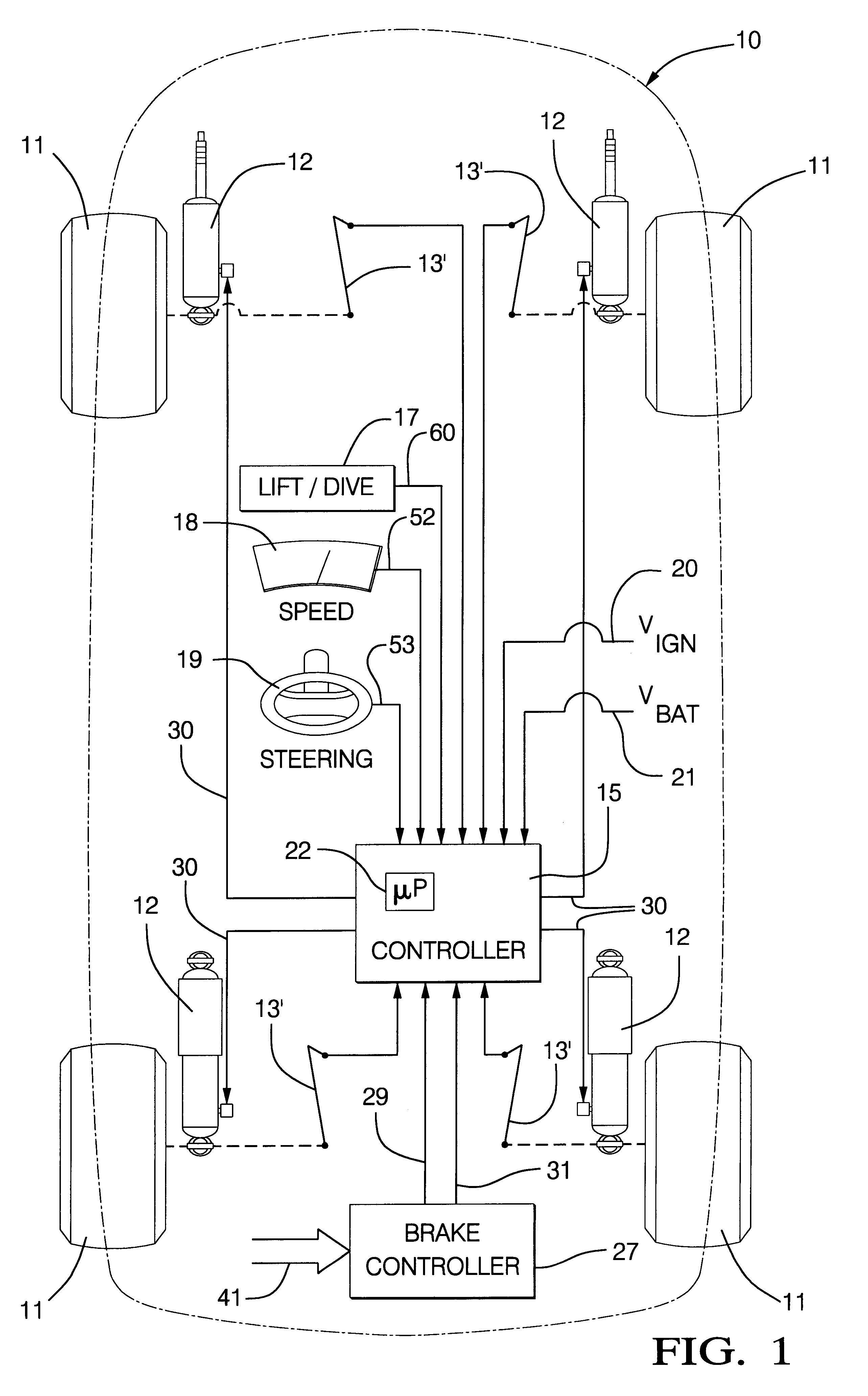
Referring to FIG. 1, an example apparatus implementing this invention comprises a vehicle body 10 supported on four wheels 11 by four suspensions including springs of a known type (not shown). Each suspension includes a variable-force, real time, controllable damper 12 connected to exert a vertical force between wheel 11 and body 10 at that suspension point. Although many such suspension arrangements are known and appropriate to this invention, actuator 12 of the preferred embodiment comprises an electrically controllable, variable force damper in parallel with a weight bearing coil spring in a parallel spring / shock absorber or McPherson strut arrangement. A description of a variable force damper suitable for use as actuator 12 is the continuously variable damper described in U.S. Pat. No. 5,282,645.

Each corner of the vehicle includes a position sensor 13 that provides an output signal indicative of the relative vertical distance between the vehicle wheel and the suspended vehicle b...


PUM


Abstract

A vehicle suspension system is responsive to an active brake signal from a brake system indicating the application of a greater braking force to one front corner brake than to the other front corner brake to affect vehicle yaw rate. The vehicle suspension system determines the relative velocities of the front corner suspension adjacent the front corner brake receiving the greater braking force and the diagonally opposed rear corner suspension and further determines a compression damping command for the front corner suspension and a rebound damping command for the rear corner suspension. While the active brake signal is present, the suspension control applies the compression damping command for the front corner suspension when its relative velocity indicates that it is in compression. While the active brake signal is present, the suspension control also applies the rebound damping command for the rear corner suspension when its relative indicates that it is in rebound.

Description

TECHNICAL FIELD OF THE INVENTIONThis invention relates to a vehicle suspension control system and method.BACKGROUND OF THE INVENTIONSome automotive vehicles are equipped with vehicle dynamic stability controls that apply braking force at specific corners of the vehicle to initiate changes in vehicle yaw rate. But the application of a braking force at a specific corner also creates a body pitch motion at that corner that can cause a tilting motion of the vehicle body around a diagonal axis. For example, in order to reverse an excessive yaw rate to the right, the stability control may apply a braking force at the left front corner of the vehicle, or a greater braking force at the left front corner than at the right front corner. But this also produces a downward pitch of the left front corner of the vehicle and a reacting upward pitch of the right rear corner of the vehicle that essentially create a tilting motion of the body about a diagonal axis with the left front corner of the veh...

Claims


Application Information

Patent Timeline
IPC IPC(8): B60G17/015G06F17/00G06F19/00G06F7/00
CPCB60G17/015B60G2400/202B60G2400/252B60G2500/10B60G2600/14B60G2600/181B60G2800/215B60G2800/93
Inventor BADENOCH, SCOTT WILSONSHAL, DAVID ANDREWFRATINI, ALBERT VICTORCONNAIR, KAREN MARIEHAMILTON, HAROLD DAVID
Owner BWI
Why Eureka
Try Eureka