
Spectrometer configured to provide simultaneous multiple intensity spectra from independent light sources

a technology of independent light sources and spectrometers, applied in the field of spectrometers, can solve the problems of inability to provide multiple simultaneous intensity spectra of light reflected from multiple portions of the surface of the film as required, and is generally considered infeasibl

Inactive Publication Date: 2001-02-06
FILMETRICS
View PDF22 Cites 73 Cited by
  • Summary
  • Abstract
  • Description
  • Claims
  • Application Information

AI Technical Summary

Benefits of technology

FIGS. 3(c) and 3(d) illustrate an embodiment of the subject invention in which f

Problems solved by technology

A problem thus arises because conventional spectrometers are capable of providing at a time the intensity spectrum of light reflected from only one portion of the surface of the film of interest.
They are thus incapable of providing multiple simultaneous intensity spectra of light reflected from multiple portions of the surface of the film as required.
Moreover, it is generally considered infeasible to use multiple conventional spectrometers in parallel, or alternatively, an optical multiplexor to allow sharing of a single spectrometer by multiple light sources, to provide the multiple simultaneous reflectance spectra as required.

Method used


Image

  • Spectrometer configured to provide simultaneous multiple intensity spectra from independent light sources
  • Spectrometer configured to provide simultaneous multiple intensity spectra from independent light sources
  • Spectrometer configured to provide simultaneous multiple intensity spectra from independent light sources

Examples


second embodiment

the spectrometer of the subject invention is illustrated in FIG. 5. According to this embodiment, light 29a, 29b is provided from sources 27a, 27b, respectively. The light 29a, 29b passes through slits 28a, 28b, respectively, whence it strikes diffraction grating 30. The impinging light is divided by the diffraction grating into a corresponding spectrum of frequency or wavelength components. Thus, for light 29a, the spectrum 29a(1)-29a(2) results, while for light 29b, the spectrum 29b(1)-29b(2) results. Each of the spectra impinges on photodiode array 31 as shown. As indicated, in this embodiment, through suitable spacing between the slits 28a, 28b, substantial overlap between the spectra 29a(1)-29a(2) and 29b(1)-29b(2) is avoided. As with the previous embodiments, the photodiode array has a plurality of receptors with at least one signal line configured in a serial or parallel format. The receptors are configured such that a value is output on the at least signal line representativ...

example

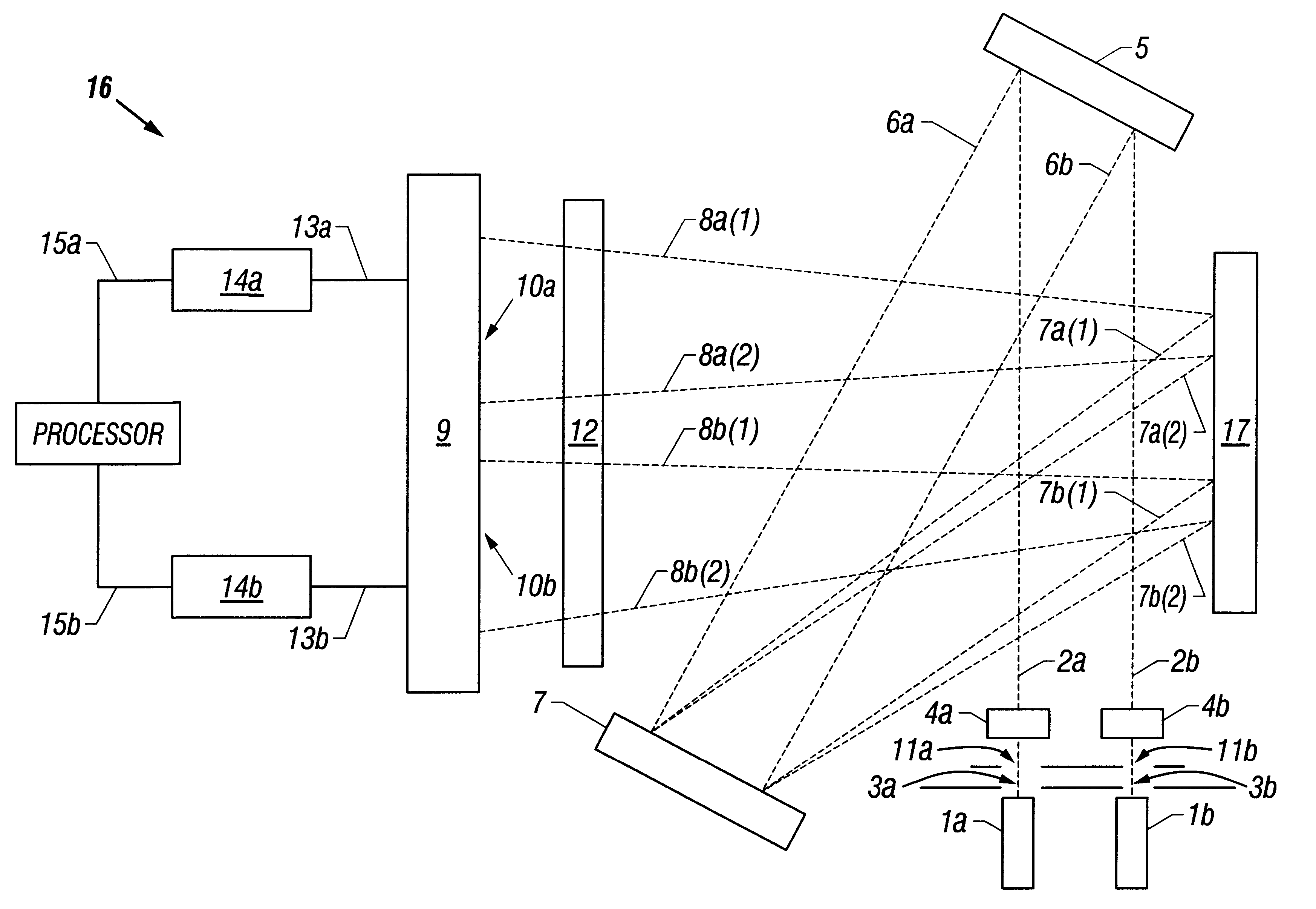
In one implementation example, spectrometer 16 was assembled by Filmetrics, Inc., San Diego, Calif., the assignee of the subject application, in the configuration shown in FIG. 1, except that the aperatures 11a , 11b, and focusing lens 12 were omitted, and three slits were provided instead of just the two slits 13a, 3b shown in FIG. 1. In this spectrometer, the photodiode array 9 is manufactured by Hamamatsu, Part No. 3923-512Q , and the diffraction grating 7 is manufactured by Optometrics, Ayer, Mass., Part No. 33-4350. The three slits are arranged in a linear fashion along an axis in a logical extension of the configuration of FIG. 1, with a spacing between the slits of 1.9 mm. Each of the three slits is manufactured by Ocean Optics, Denedin, Fla., Part No. SLIT, and has a width of 10 microns. The wavelength region of interest depends on the desired thickness measurement range. The following table correlates the wavelength range of interest with the desired thickness measurement r...


PUM


Abstract

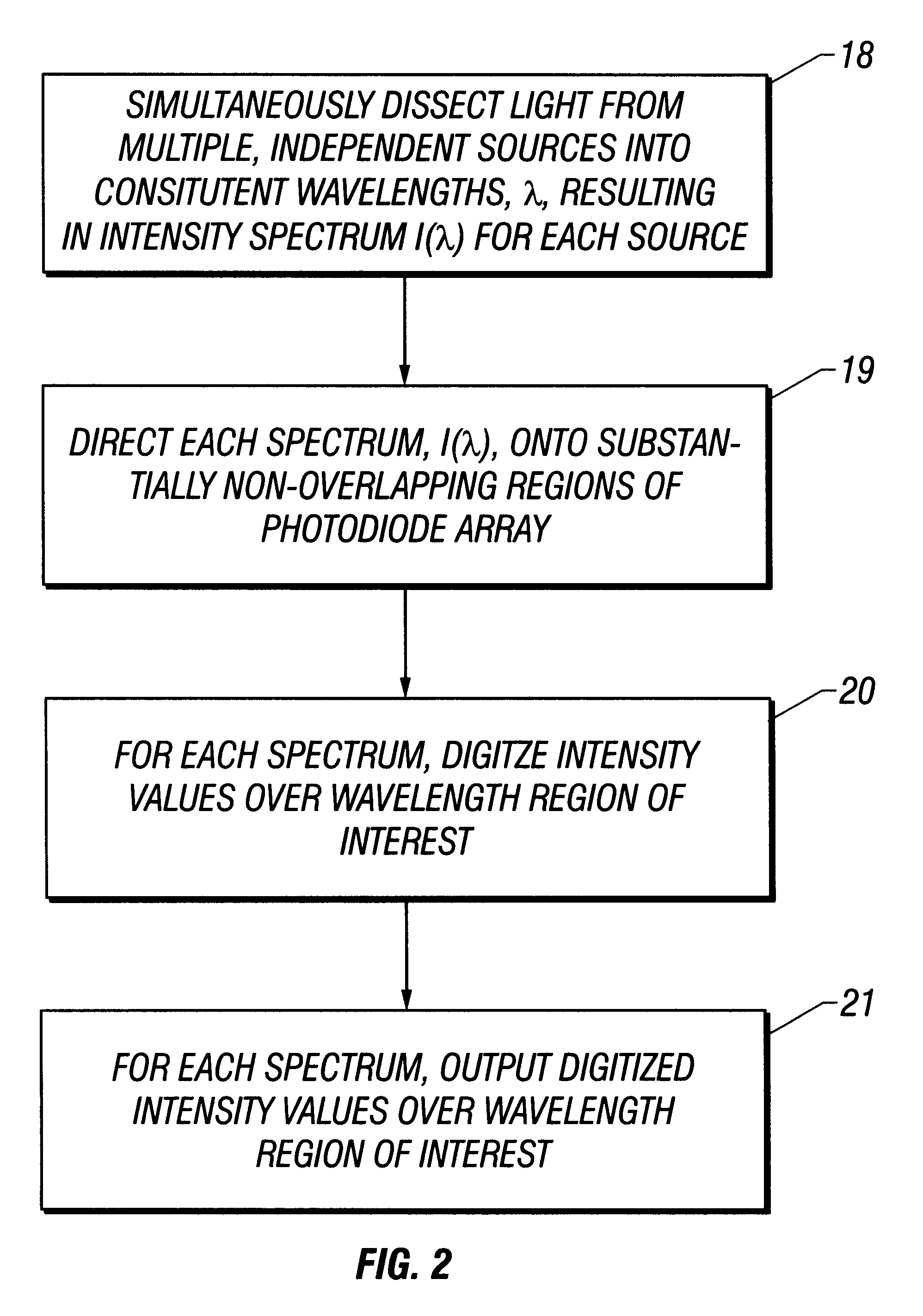
A spectrometer for providing multiple, simultaneous spectra from independent light sources is described characterized in that light from the multiple sources is directed to different portions of a diffraction grating, and the wavelength components of the resultant spectra are directed to at least one receptor.

Description

I. BACKGROUND OF THE INVENTIONThis invention relates generally to the field of spectrometers, and more specifically, to a spectrometer which is configured to provide simultaneous, multiple intensity spectra from independent light sources.In many applications, it is desirable to be able to measure the thickness of a film at more than one location simultaneously. One such application is the manufacture of digital video disks (DVD) in which simultaneous measurement of film thickness over the surface of the disk helps to ensure a high degree of uniformity of film thickness in the final manufactured product. Another example is the manufacture and processing of semiconductor wafers. There, it is frequently desirable to deposit, using chemical vapor deposition (CVD) or the like, a film onto a substrate or a multi-film or patterned sample, or polish, using chemical mechanical planarization (CMP) or the like, an existing film on such a sample, such that the film has a high degree of uniformi...

Claims


Application Information

Patent Timeline
IPC IPC(8): G01B11/06G01J3/30G01J3/36G01J3/28
CPCG01B11/0625G01J3/2803G01J3/36
Inventor CHALMERS, SCOTT A.GEELS, RANDALL S.
Owner FILMETRICS
Learn More