
High conformality antireflective coating compositions

Inactive Publication Date: 2001-02-20
SHIPLEY CO LLC
View PDF25 Cites 65 Cited by
  • Summary
  • Abstract
  • Description
  • Claims
  • Application Information

AI Technical Summary

Benefits of technology

Alternatively, the ARC resin binder component can comprise a polymer blend where only a portion of the blend consists of high molecular weight materials. Thus, for example, extremely high polydispersity polymers which contain high molecular weight species can be employed. Such high polydispersity polymers can be readily prepared e.g. by blending different lots of polymers having significantly different M.sub.w or M.sub.w. It is also not necessary that a blend partner be an identical polymer.

Problems solved by technology

Reflection of activating radiation used to expose a photoresist often poses limits on resolution of the image patterned in the photoresist layer.
Reflection of radiation from the substrate / photoresist interface can produce spatial variations in the radiation intensity in the photoresist, resulting in non-uniform photoresist linewidth upon development.
Radiation also can scatter from the substrate / photoresist interface into regions of the photoresist where exposure is not intended, again resulting in linewidth variations.
The amount of scattering and reflection will typically vary from region to region, resulting in further linewidth non-uniformity.
Due to radiation reflection at the photoresist / substrate interface, however, constructive and destructive interference is particularly significant when monochromatic or quasi-monochromatic radiation is used for photoresist exposure.
In such cases the reflected light interferes with the incident light to form standing waves within the photoresist.
In the case of highly reflective substrate regions, the problem is exacerbated since large amplitude standing waves create thin layers of underexposed photoresist at the wave minima.
The underexposed layers can prevent complete photoresist development causing edge acuity problems in the photoresist profile.
If the photoresist thickness is non-uniform, the problem becomes more severe, resulting in variable linewidths.
Variations in substrate topography also give rise to resolution-limiting reflection problems.
Any image on a substrate can cause impinging radiation to scatter or reflect in various uncontrolled directions, affecting the uniformity of photoresist development.
As substrate topography becomes more complex with efforts to design more complex circuits, the effects of reflected radiation become more critical.
For example, metal interconnects used on many microelectronic substrates are particularly problematic due to their topography and regions of high reflectivity.
Thus, the use of the shorter wavelengths has exacerbated the problems of reflection from a substrate surface.
While it has been found that prior antireflective compositions may be effective for many antireflective applications, prior compositions also may pose some potential performance limitations, e.g. when the antireflective compositions are used with resist compositions to pattern features of sub-micron or sub-half micron dimensions.
More particularly, antireflective compositions are perhaps most frequently applied over topography where substrate reflections can be especially problematic.
However, current antireflective compositions often do not form uniform coating layers over such topography.
This can result in additional etch time to clear the valley regions, ineffective amounts of ARC present on the high points and edges and variations in substrate reflectivity due to departure of the ARC coating layer thickness from the desired quarter wave thickness that can provide optimal anti-reflection properties.

Method used


Image

  • High conformality antireflective coating compositions
  • High conformality antireflective coating compositions
  • High conformality antireflective coating compositions

Examples


example 1

Preparation of high molecular polymers

Preferred polymers for use in ARCs of the invention can be prepared as follows.

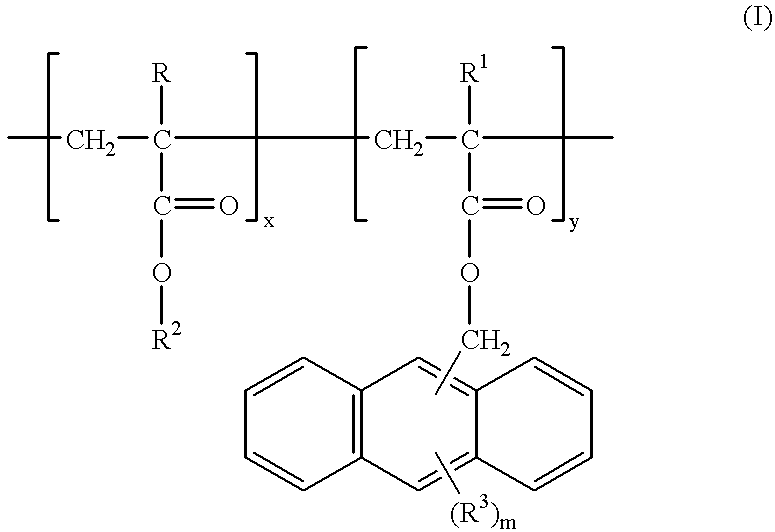
Hydroxyethyl methacrylate (HEMA)Imethylanthracene methacrylate (ANTMA) copolymer (Formula I above) are suitably prepared by charging a 300 ml 3N round bottom flask equipped with magnetic stirrer, condenser, nitrogen and vacuum inlet with 16.0 g (0.1229 mol) HEMA (purified by distillation), 8.49 g (0.0307 mol) methylanthracene methacrylate, 0.2449 g (1 wt. %) AIBN and 180 ml THF. Other amounts of HEMA and ANTMA monomers can be suitably employed to provide HEMA / ANTMA copolymers having other HEMA and / or ANTMA units mole percents. The reaction flask is quenched in liquid nitrogen while being purged with nitrogen. When the contents of the reaction flask are frozen, the flask is evacuated, then purged with nitrogen (3 times). The reaction mixture is stirred under reflux until reaction completion, e.g. about 18 hours. The pale yellow polymer is precipitated into 3000 ml ethe...

example 2

Preparation and processing of ARCS of the invention

Six antireflective compositions of the invention (referred to as ARCs 1-6)were prepared by mixing the components set forth below, with component amounts pressed as parts by weight based on total weight of solids of the ARC. All the ARCs had the same components and amounts thereof, expect for the Resin binder component. ARC 1 had a resin binder component that consisted of Polymer 1; ARC 2 had a resin binder component that consisted of Polymer 2; ARC 3 had a resin binder component that consisted of Polymer 3; ARC 4 had a resin binder component that consisted of Polymer 4; ARC 5 had a resin binder component that consisted of Polymer 5; and ARC 6 had a resin binder component that consisted of Polymer 6.

Components of ARCs 1-6:

1) Resin binder: 86.4 weight % of one of Polymers 1-6

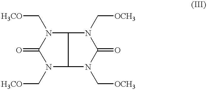
2) Crosslinker: 12 weight % Powderlink 1174 (American Cyanamid)

3) Thermal acid generator: 1.5 weight % p-nitrobenzyltosylate

4) Surfactant: 0.1 weight % FC-431 (3M...


PUM


Abstract

The present invention provides new light absorbing compositions suitable for use as antireflective coating compositions ("ARCs"), particularly for deep UV applications. The antireflective compositions of the invention in general comprise a resin binder component that contains a high molecular weight polymer, e.g. a polymer having an Mw of at least about 40,000 daltons. ARCs of the invention exhibit exceptional conformality upon application to a substrate surface. For example, ARCs of the invention can coat substantial topography such as vertical and sloping steps with high conformality.

Description

1. Field of the InventionThe present invention relates to compositions that reduce reflection of exposing radiation from a substrate back into an overcoated photoresist layer. More particularly, the invention relates to antireflective coating compositions that can be applied as coating layers that are highly conformal with respect to an underlying substrate.2. Background ArtPhotoresists are photosensitive films used for transfer of an image to a substrate. A coating layer of a photoresist is formed on a substrate and the photoresist layer is then exposed through a photomask to a source of activating radiation. The photomask has areas that are opaque to activating radiation and other areas that are transparent to activating radiation. Exposure to activating radiation provides a photoinduced chemical transformation of the photoresist coating to thereby transfer the pattern of the photomask to the photoresist coated substrate. Following exposure, the photoresist is developed to provide...

Claims


Application Information

Patent Timeline
IPC IPC(8): G03F7/09G03F7/004G03F7/039G03F7/11H01L21/027
CPCG03F7/091G03F7/0046G03F7/0382G03F7/0392G03F7/11G03F7/2041
Inventor PAVELCHEK, EDWARD K.DOCANTO, MANUELADAMS, TIMOTHY G.
Owner SHIPLEY CO LLC
Learn More