Insulating container

a technology of heat-insulating containers and containers, which is applied in the field of heat-insulating containers, can solve the problems of irregular bottom of the heat-insulating container, inability to give the high-grade appearance of design, and recesses on the outer periphery of the container, etc., and achieves the effects of improving rigidity, and reducing the risk of damag

Inactive Publication Date: 2001-02-27
DAI NIPPON PRINTING CO LTD
View PDF19 Cites 118 Cited by
  • Summary
  • Abstract
  • Description
  • Claims
  • Application Information

AI Technical Summary

Benefits of technology

When the material used for the tubular member 20, 80 is subjected to a resin coating process or a resin impregnating process, it is possible to improve the rigidity, the proof compressive property, the proof collapsing property and the like of the entirety of the heat-insulating container 30, 90 so as to protect the contents received in the container from an external force applied to thereto during distribution of the container.
The heat-insulating container, which has not only a stable heat-insulating property over its entirety, but also a sufficient rigidity to prevent the occurrence of deformation of the container permits to improve safety and reliability required for a container, which is to be filled with boiling water to make an instant dried food eatable received in the container, and is to be held at its shell or the handle with a hand in order to eat the food. Such properties are considered as important factors especially for aged persons, physically handicapped persons and children, as well as essential factors required for barrier-free goods. With respect to the tubular member 80, the rigidity of the handle itself and especially the easily handling property are considered as important factors. Provision of the handle having an optimized shape is considered to be one of the essential factors required for barrier-free goods.
When the heat-insulating container 90, which has a sufficient heat-insulating property and is filled with boiling water, is held a single hand, the direct holding of the shell of the container can provide a more stable condition in comparison with the holding of the handle of the container. It is however necessary to increase the distance between the dual side wall members 51, 55 in order to impart the sufficient heat-insulating property to the container. As a result, the thickness of the side wall of the heat-insulating container 90 increases so that the so-called "stacking pitch" (i.e., the distance between the containers arranged in a stacked state) increases, thus deteriorating transportation efficiency of the containers. According to the heat-insulating container 90 having the handle of the present invention, the moderate heat-insulating property that is ensured by the dual side walls 51, 55 suffices with the result that the thickness of the side wall can be decreased smaller than the conventional heat-insulating container. Consequently, it is possible to provide the heat-insulating containers, which have the small stacking pitch and excellent transportation efficiency.
The heat-insulating container 30, 90 of the present invention is formed of paper so as to be disposed easily without being subjected to segregated disposal. Although the heat-insulating container 30, 90 of the present invention has sufficient rigidity for preventing its deformation, it can easily be collapsed by a small force given by a hand. Accordingly, it is possible to decrease the volume of the container in the light of disposal thereof. The container of the present invention has an excellent disposability and a smaller adverse influence on environment in comparison with the other conventional heat-insulating container using foamed plastic as the heat-insulating material.
In addition, no uneven portion is formed on the side shell-wall 1, 51 of the heat-insulating container 30, 90 of the present invention and in other words, the side shell-wall has the smooth outer surface. The inward curled portion 6, 59 of the tubular member 20, 80 locates at the bottom of the container so as to reveal a moderate curvature. The heat-insulating container 30 therefore has an elaborated design as a cup-shaped container. The gap formed between the cup body 10, 70 and the side wall 1, 5, 51, 55 of the tubular member 20, 80 at the bottom of the container is sealed with the inward curled portion 6, 59 so as to prevent dust or foreign matters from entering the heat-insulating space 31, 91 and to prevent liquid from being absorbed from the edge of the sheet of paper for forming the cup body 10. The heat-insulating container 30, 90 of the present invention can be kept hygienic.
The tubular member 20, 80 has a high degree of freedom in printing, and can therefore be subjected without specific restriction not only to the conventional printing process such as an offset printing, a gravure printing, a flexo graphic printing or the like, but also to the conventional process such as an overcoating process, a stamping process, an embossing process or the like, which are to be carried out after the completion of the printing process. As a result, such printing and processing properties can provide an excellent aesthetic effect in cooperation with the smooth outer surface of the container mentioned above. It is further possible to form an overcoating layer of varnish on the side wall of the tubular member 20, 80 and / or the surface of the inward curled portion 6, 59 so as to prevent these portions from being wetted and becoming unclean.

Problems solved by technology

The heat-insulating member of the heat-insulating container has the above-mentioned irregularity so that characters, designs or the like printed on its surface appear extremely unclearly, thus making it impossible to give the high-grade appearance of design to the container.
However, the recesses appearing on the outer periphery of the container do not provide complete solution of the above-mentioned problems.
However, the bottom of the heat-insulating container may have irregularity in the joined portions of the heat-insulating member and the liner.
Dirt or liquid may enter the gap of the bottom of the container, thus causing insanitary problems.
The additional liner provides an increased production cost.
When the container is actually held at the central portion of the side shell-wall thereof with a hand, the tubular member may however easily be deformed inward to decrease the capacity of the heat-insulating space, thus deteriorating the heat-insulating property.

Method used


Image

  • Insulating container
  • Insulating container
  • Insulating container

Examples


first embodiment

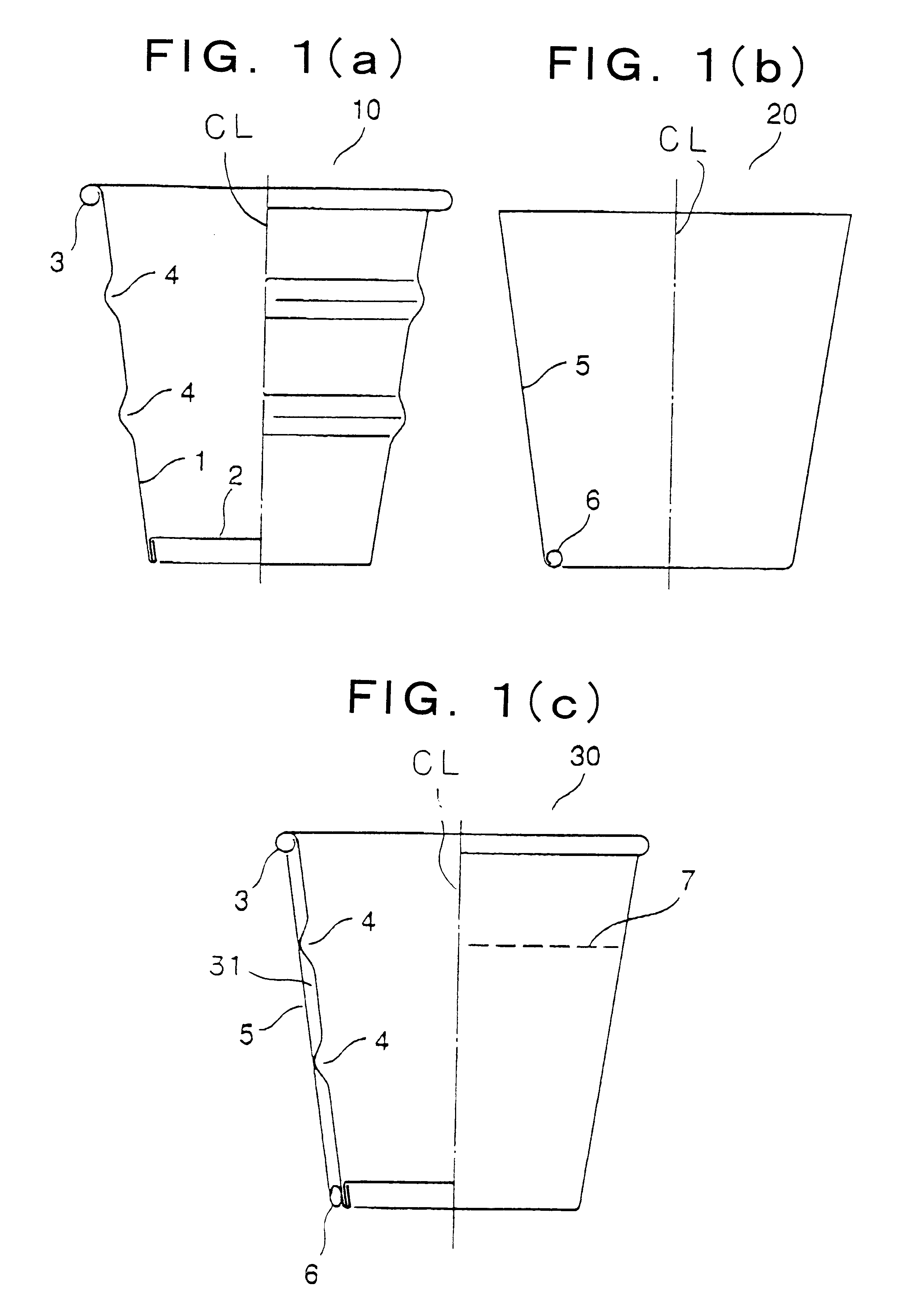
The sample of the heat-insulating container 30 of the present invention was prepared in accordance with the following manner.

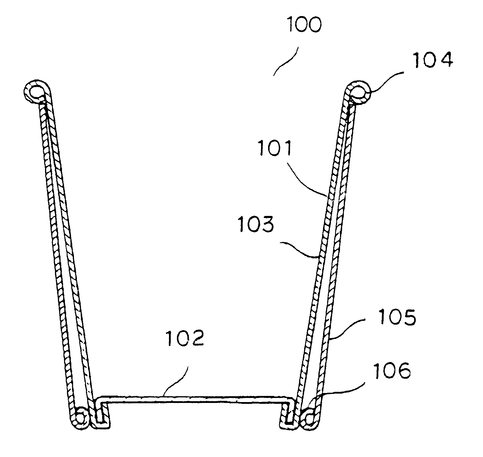
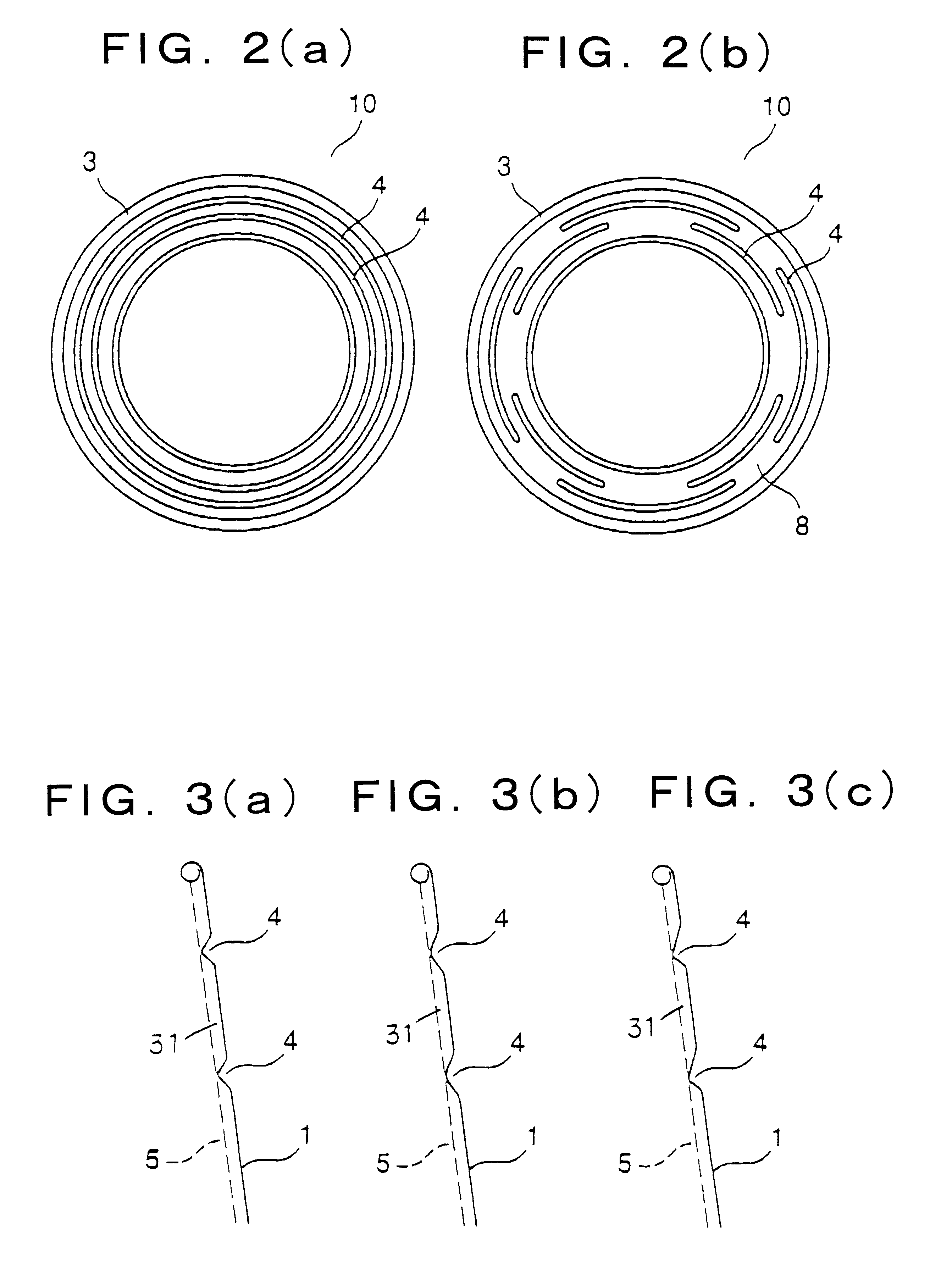
The tubular member 20 was brought into contact with the cup body 10 at the two horizontal ribs 4 and the side wall of the bottom and the contact portions were joined with each other by means of an acrylic emulsion type adhesive agent. The sample of the invention having the heat-insulating space 31, in which the upper gap was 1 mm and the lower gap was 2 mm, was prepared in this manner. The heat-insulating container 100 as shown in FIG. 1, which had no horizontal rib 4, was prepared as a comparative example.

Boiling water having a temperature of 95.degree. C. was poured into each of the samples in an amount of 240 cc so as to reach the level line for the boiling water. After the lapse of time of 2 or 3 minutes, the middle portion of the shell of each of the samples was held by a hand to make a tactile inspection of temperature on the outer surface of each of the...

example 2

The sample of the heat-insulating container 90 of the second embodiment of the present invention was prepared in accordance with the following manner. Dimensions and angles of the components of the container are indicated in FIG. 10.

The cup body 70 was provided with a single horizontal rib 57. The single horizontal rib 57 was brought into contact with the tubular member 80. The tubular member 80 and the cup body 70 were joined with each other at their lowermost contact portions by an acrylic emulsion type adhesive agent. The conventional double-layer type heat-insulating container having no handle (see FIG. 11) was prepared as a comparative example.

Boiling water having a temperature of 95.degree. C. was poured into each of the samples in an amount of 240 cc so as to reach the level line for the boiling water. After the lapse of time of 2 or 3 minutes, the handle of the sample of the invention was held with a hand and the comparative example was held at its portion locating below the...


PUM


Abstract

A heat-insulating container comprises a paper cup body having an inner surface, an upper open end, a shell member and a bottom, the inner surface being coated with polyolefine resin, the upper open end having an outward curled portion and the shell member having a side wall on which at least one rib is formed; and a tubular member being formed of paper and having an inverse truncated conical shape, the tubular member having at a lower end thereof an inward curled portion. The tubular member is combined with an outer periphery of the paper cup body so as to come into contact with the paper cup body in contact portions provided on the at least one rib of the paper cup body and on an outer periphery of an lower end of the side wall of the shell member. According to such a structure, it is possible to provide the heat-insulating container, which has a stable heat-insulating property, a high grade design, a high degree of freedom in indication by printing on the outer surface of the container, and a lower production cost.

Description

The present invention relates to a heat-insulating container made of paper, which is used for an instant dried food to be become eatable by pouring boiling water over it or food to be heated or cooked by means of a microwave oven.As a heat-insulating container made paper mainly used for instant dried Chinese noodles, there has widely been used a container in which a paper cup body surrounded over its outer periphery with a heat-insulating corrugated member having narrow projections and recesses arranged alternately.The heat-insulating member of the heat-insulating container has the above-mentioned irregularity so that characters, designs or the like printed on its surface appear extremely unclearly, thus making it impossible to give the high-grade appearance of design to the container.In Japanese Patent Provisional Publication No. H8-113274, there is proposed a heat-insulating container in which the width of the recesses of the heat-insulating member is made smaller than that of the...

Claims


Application Information

Patent Timeline
Patent Type & Authority Patents(United States)
IPC IPC(8): B31B7/00B65D3/22B65D81/38B65D25/28B65D3/00B65D3/02B31B50/00
CPCB31B7/00B65D3/22B65D25/2847B65D81/3869B31B2217/0038B31B2120/40B31B2105/00B31B2105/0022B31C7/02
Inventor MOCHIZUKI, YOICHIHIRAI, YUICHIYAMADA, KAZUKI
Owner DAI NIPPON PRINTING CO LTD
Why Eureka
Try Eureka