

Gyrator with loop amplifiers connected to inductive elements
- Summary
- Abstract
- Description
- Claims
- Application Information
AI Technical Summary
Benefits of technology
Problems solved by technology
Method used
Image

Examples
example 2
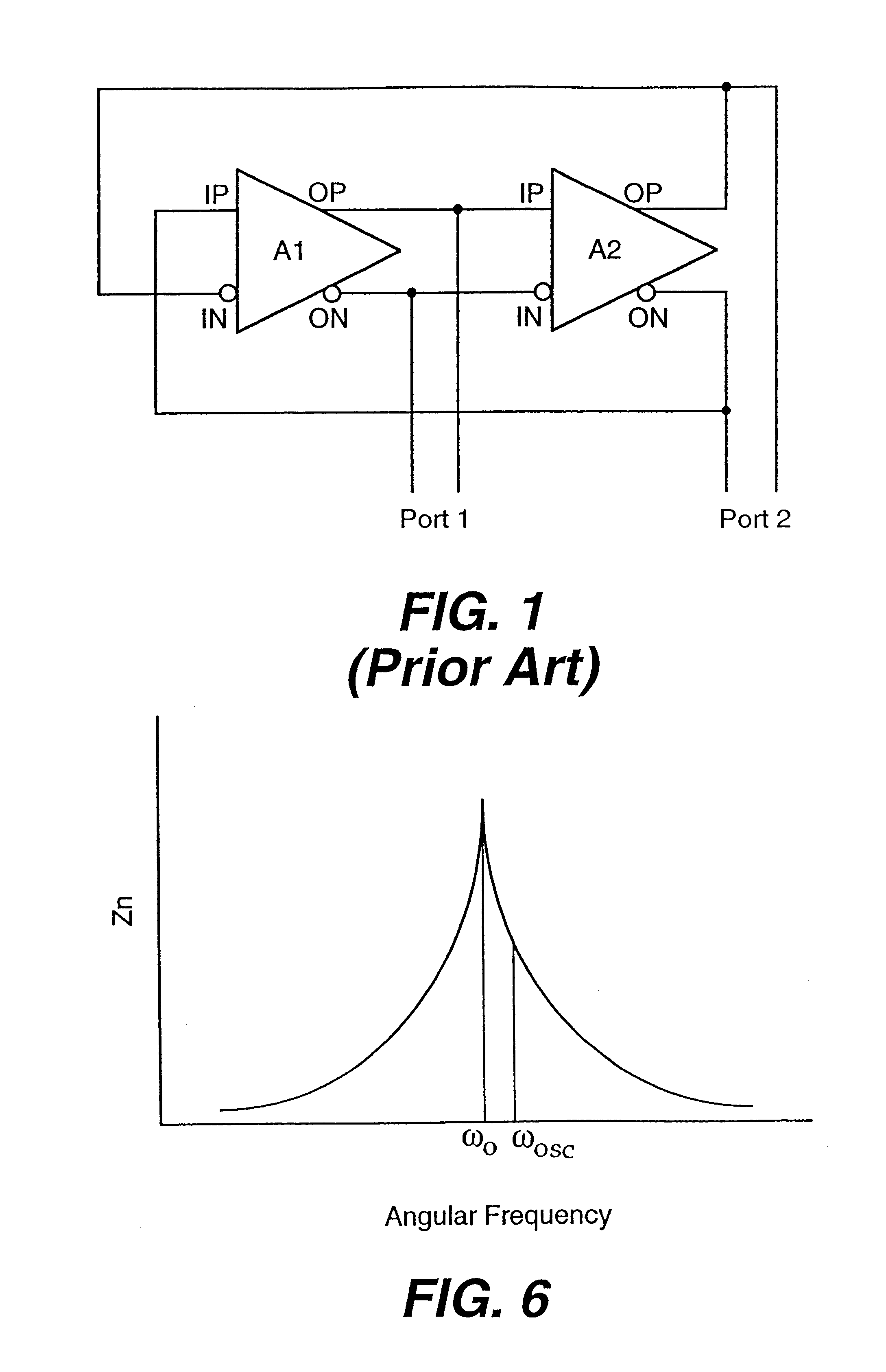
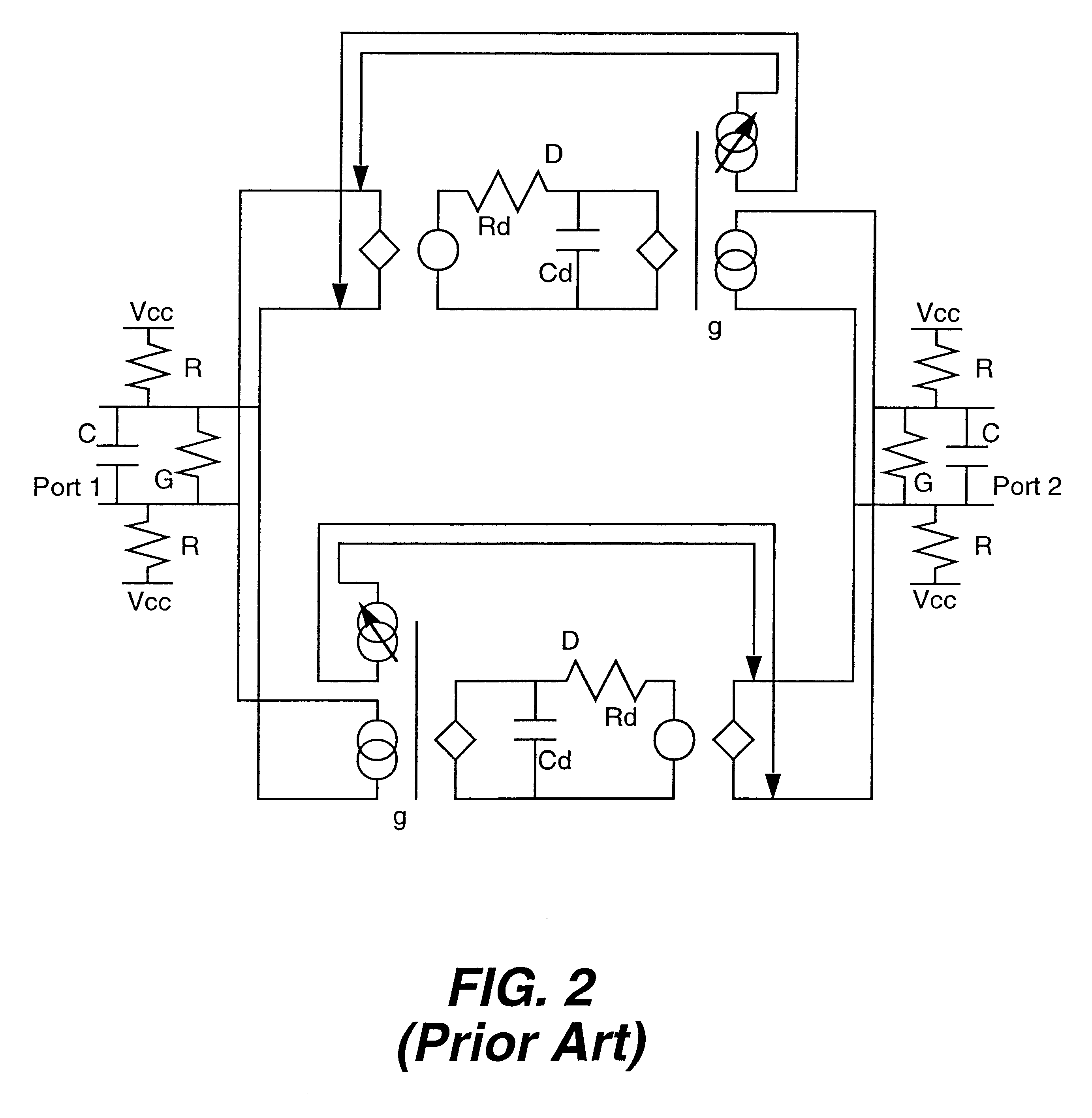
Prior Art Gyrator
Resonant Frequency=1 GHz
Nodal Capacitance C=1 pF
(consisting of non-linear circuit parasitics)
Shunt Load Resistance=350 .OMEGA.
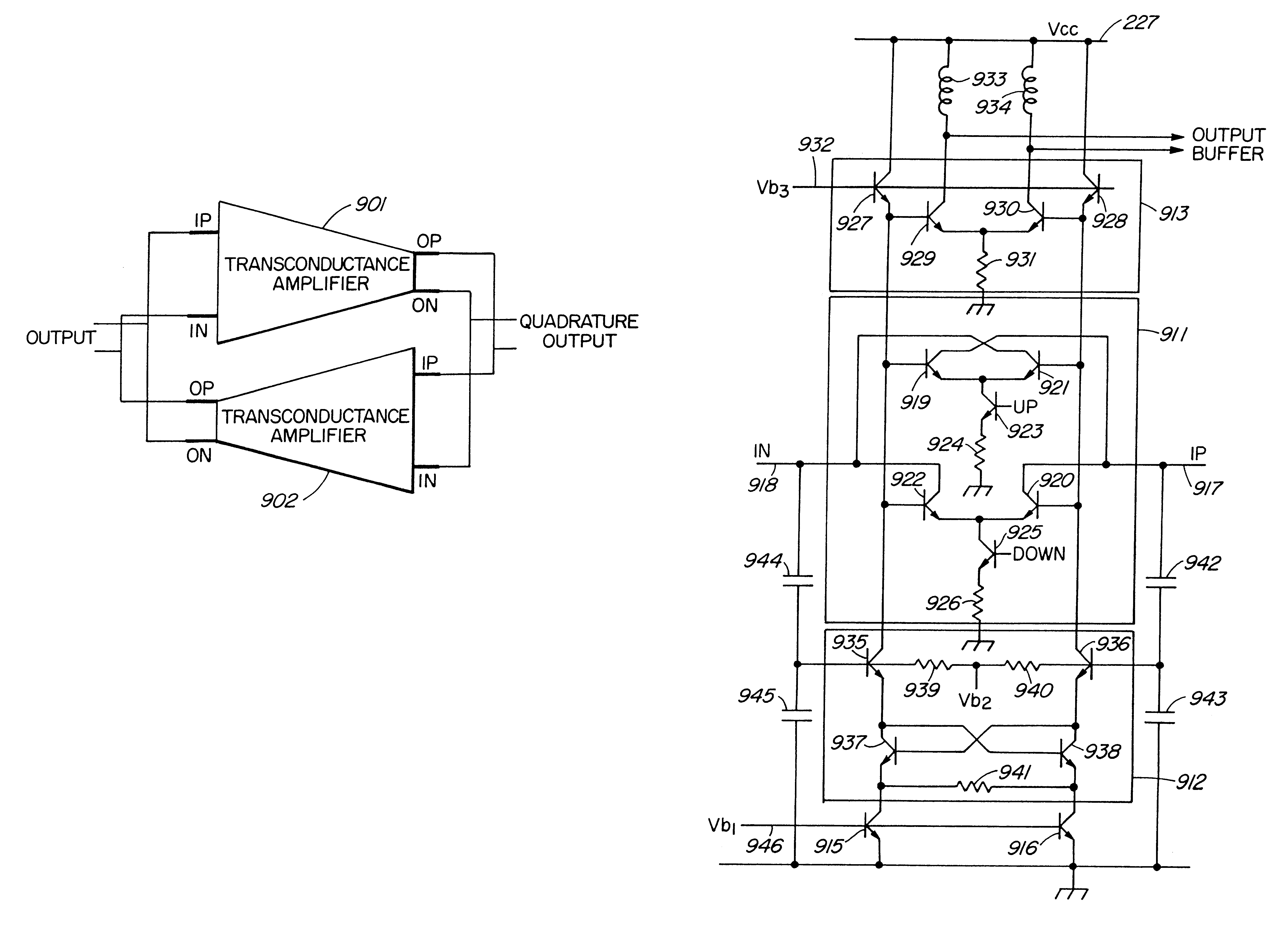
Embodiment Gyrator (see FIG. 7)
Oscillation Frequency=1 GHz
Inductance L=12.7 nH
Additional Shunt Capacitance Cad=2 pF
Note that the self resonant frequency of the parallel inductor capacitor combination is 0.816 GHz. The equivalent nodal capacitance is still 1 pF. In this example, the oscillating angular frequency .omega..sub.osc is substantially the same as the resonant angular frequency .omega..sub.o.
example 3
Prior Art Gyrator
Resonant Frequency=1 GHz
Nodal Capacitance C=1 pF
Shunt Load Resistance=350 .OMEGA.
embodiment (see fig.8)
Embodiment (see FIG. 8)
Oscillation Frequency=2 GHz
Inductance L=3.6 nH
Additional Shunt Capacitance Cad=1 pF
In this example, the gyrator oscillation frequency can be increased to a 2 GHz oscillation frequency while at the same time doubling the nodal capacitance linearity.
Thus, the ability to double the gyrator frequency while doubling the nodal capacitance can be achieved by replacing the shunt nodal load resistor with a shunt lossy inductor which at the same time achieves the purpose of discriminating against injected power supply noise. The filtering action of the inductor depends on the inductor capacitor combination and is enhanced where the nodal capacitance is increased. In the case of example 2, the attenuation of high frequency power supply noise increases at 12 dB per octave above 1 GHz as compared to the unmodified gyrator with 6 dB per octave. Thus, the improved gyrator has 43.6 dB attenuation of 10 GHz noise as compared to the unmodified gyrator ...
PUM
 Abstract
Description
Claims
Application Information