Systems and methods employing a rotary track for machining and manufacturing

a technology of machining and manufacturing, applied in the direction of gearing, mechanical control devices, instruments, etc., can solve the problems of unrealistic high expectations of technical expertise available to users of cam software, limited range of movement, and most machine tools today fail to provide the necessary precision, etc., to achieve greater range of positioning and orientation, and reduce thermal expansion

Inactive Publication Date: 2001-03-06
HEXEL CORP
View PDF9 Cites 193 Cited by
  • Summary
  • Abstract
  • Description
  • Claims
  • Application Information

AI Technical Summary

Benefits of technology

It is an object of the invention to provide systems and methods that provide improved platform systems which are facile to manufacture, which can have reduced thermal expansion and which can achieve greater ranges of positioning and orientation.

Problems solved by technology

However, most machine tools today fail to provide the necessary precision, in part due to their limited range of movement, high cost, inability to recognize their own work space to plan complex motion activity, and unrealistically high expectations of technical expertise available for the users of CAM software.
Although these movable structures can work well, the supportive leg assemblies are generally quite complex, costly and difficult to manufacture.
Moreover, the complexity of the legs, typically including inter-locking members, are subject to problematic thermal expansion, that can change the length of the extension arm and therefore interfere with the accurate placement of the point on the platform.
In addition, these structures have limits within which the platform may be positioned and oriented.

Method used


Image

  • Systems and methods employing a rotary track for machining and manufacturing
  • Systems and methods employing a rotary track for machining and manufacturing
  • Systems and methods employing a rotary track for machining and manufacturing

Examples


Embodiment Construction

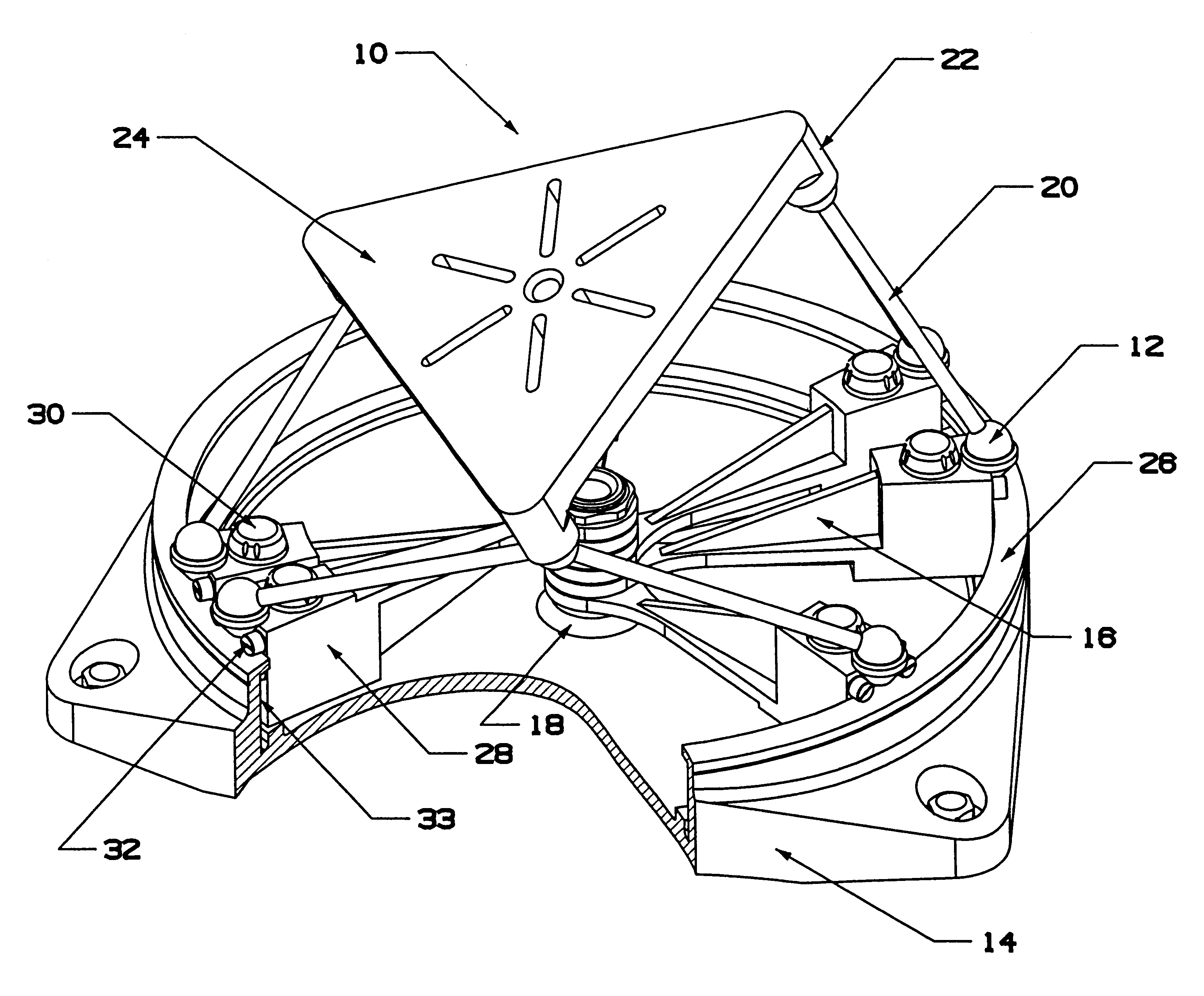
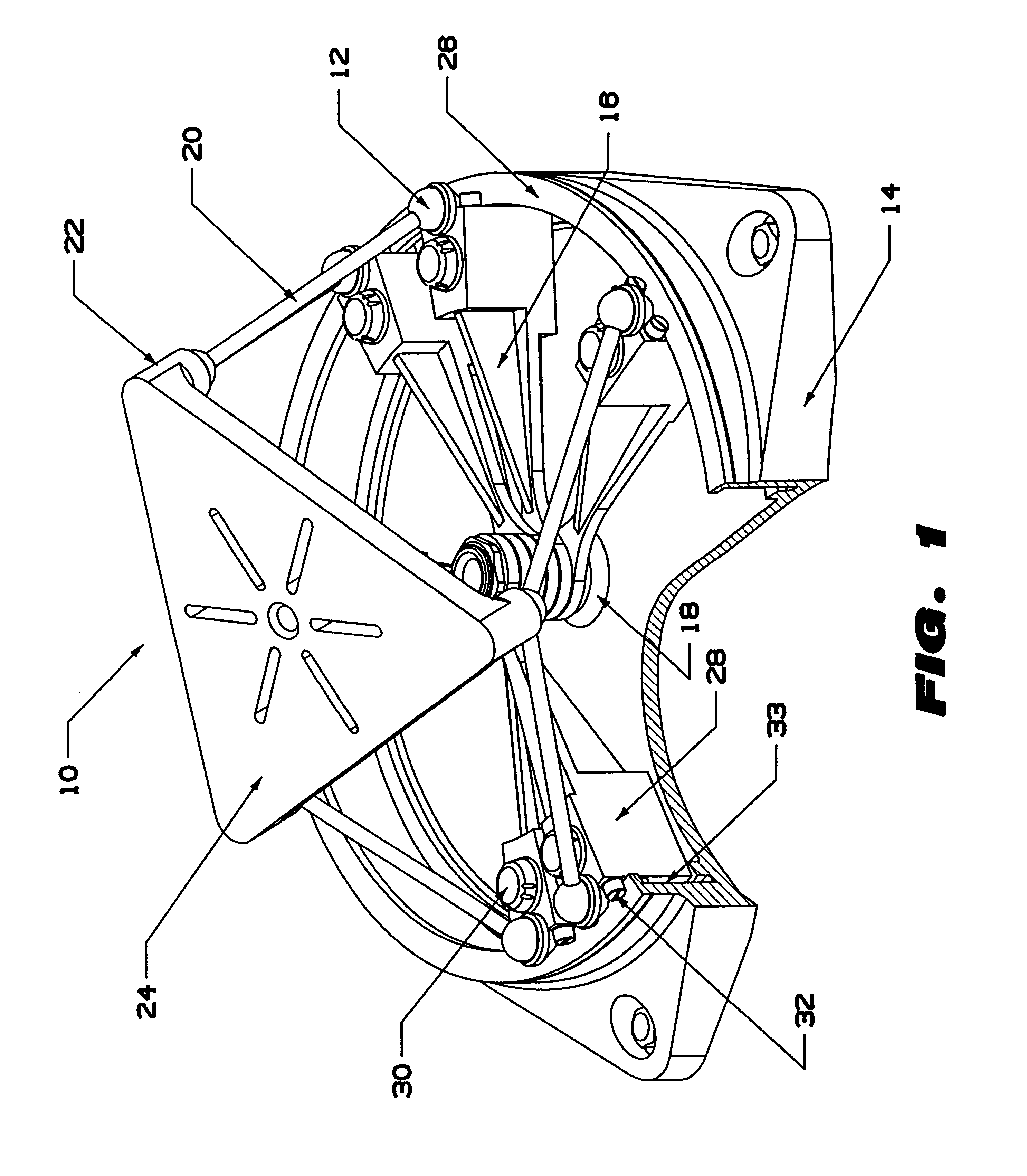
FIG. 1 depicts one embodiment of a system having a rotary track and a working surface that is positioned and oriented by legs carried by trucks moveably coupled to the rotary track.

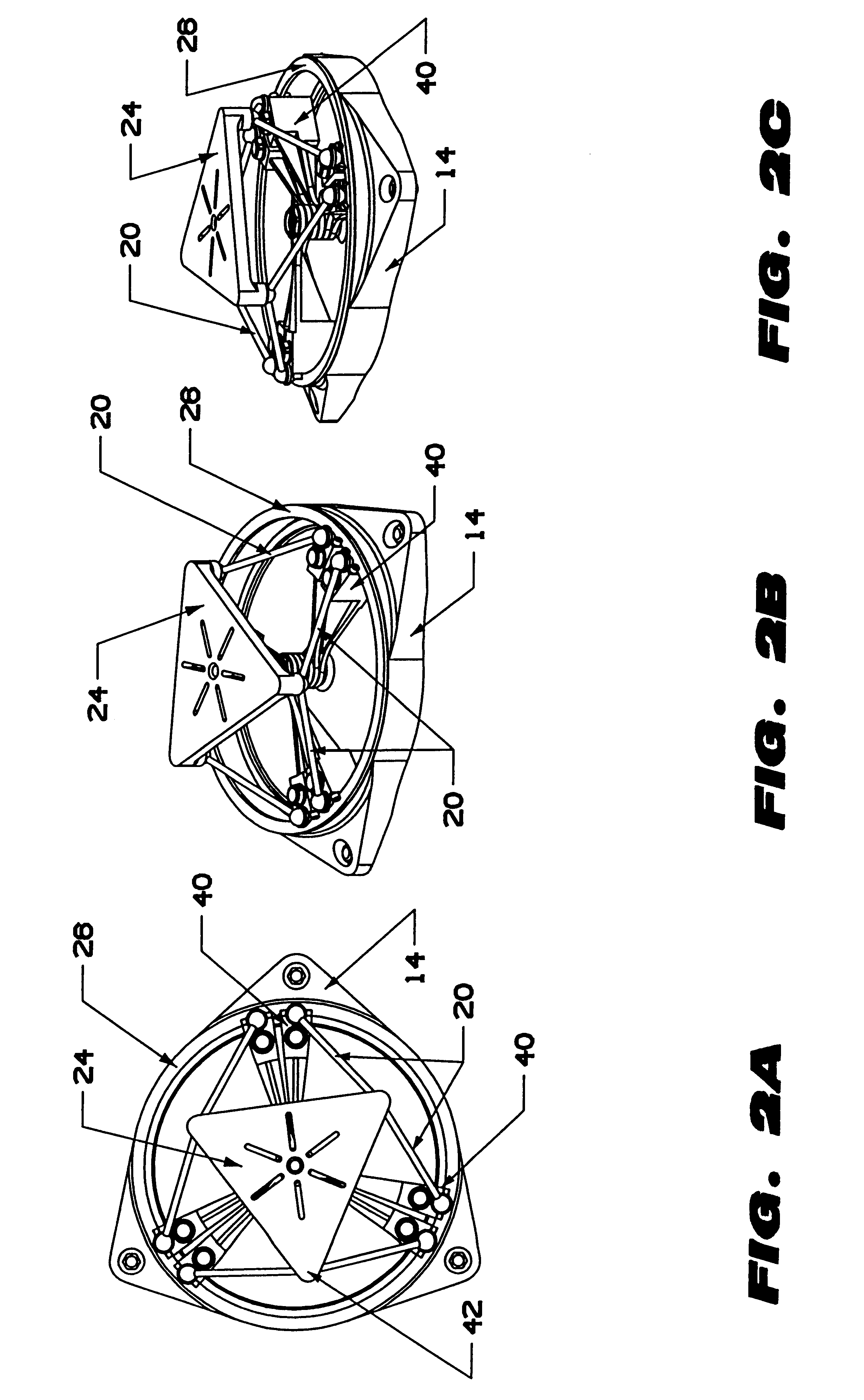
FIGS. 2A-2C depict the embodiment of FIG. 1 wherein the working surface is in a parallel orientation relative to a reference surface defined by the rotary track.

FIGS. 3A-3D depict schematically an embodiment of the invention having a working surface supported by a plurality of legs wherein the reference surface is in a parallel orientation and lowered position relative to a reference surface defined by a rotary track.

FIGS. 4A-4D depict schematically the embodiment of FIGS. 3A-3D wherein the working surface is in a parallel orientation and raised position relative to the reference surface.

FIGS. 5A-5D depict schematically the embodiment of FIGS. 3A-3D wherein the working surface is in an inclined orientation relative to the reference surface.

FIGS. 6A-6D depict schematically the embodiment of FIGS. 3A-3D whe...


PUM


Abstract

The systems and methods described herein include hexapod systems, Stewart platform systems and other mechanical movement systems, in which a set of independently moveable trucks support legs that couple to a working surface capable of holding a machine tool or other end-effector, and preferably wherein the trucks travel across a reference surface, such as around the circumference of a circle or along some other pre-defined geometrical pattern or track. For example, as described herein, the systems include Stewart platform machines that have six supportive legs each of which connects to a truck that can travel independently along a track. By coordinating the movement of these six trucks, the working surface can be moved in three dimensional space and can be oriented about three axes, providing control of roll, pitch and yaw.

Description

The invention relates to devices for manufacturing and machining, particularly devices that include a movable platform for positioning a tool in space.High precision automated manufacturing, such as computer aided manufacturing (CAM), requires that the position of a tool be precisely known in space. However, most machine tools today fail to provide the necessary precision, in part due to their limited range of movement, high cost, inability to recognize their own work space to plan complex motion activity, and unrealistically high expectations of technical expertise available for the users of CAM software. To overcome these problems, engineers have developed mechanical movement systems that include a movable platform that is mounted with substantial freedom in translation and rotation by means of a plurality of legs the length and angular orientation of which are controllably adjustable. Through coordinated control of the effective length of the legs, the platform can be precisely m...

Claims


Application Information

Patent Timeline
Patent Type & Authority Patents(United States)
IPC IPC(8): B23Q1/54B23Q3/18B23Q1/25B23Q1/00B23Q1/44B23Q5/26F16H21/46
CPCB23Q1/5462B23Q3/18Y10T74/20207Y10T74/20335
Inventor YAU, CHI LAM
Owner HEXEL CORP
Why Eureka
Try Eureka