Stent

a technology of stents and lasers, applied in the field of stent fabrication methods, can solve the problem of too large spot size of lasers, and achieve the effect of intricate and/or delicate designs

Inactive Publication Date: 2001-03-06
MEDINOL LTD
View PDF20 Cites 101 Cited by
  • Summary
  • Abstract
  • Description
  • Claims
  • Application Information

AI Technical Summary

Benefits of technology

It is, therefore, an object of the present invention to provide a stent fabrication method which can produce stents with relatively intricate and / or delicate designs.

Problems solved by technology

However, for more delicate and / or intricate shapes, the spot size of the laser is too large.

Method used


Image

  • Stent
  • Stent
  • Stent

Examples


Embodiment Construction

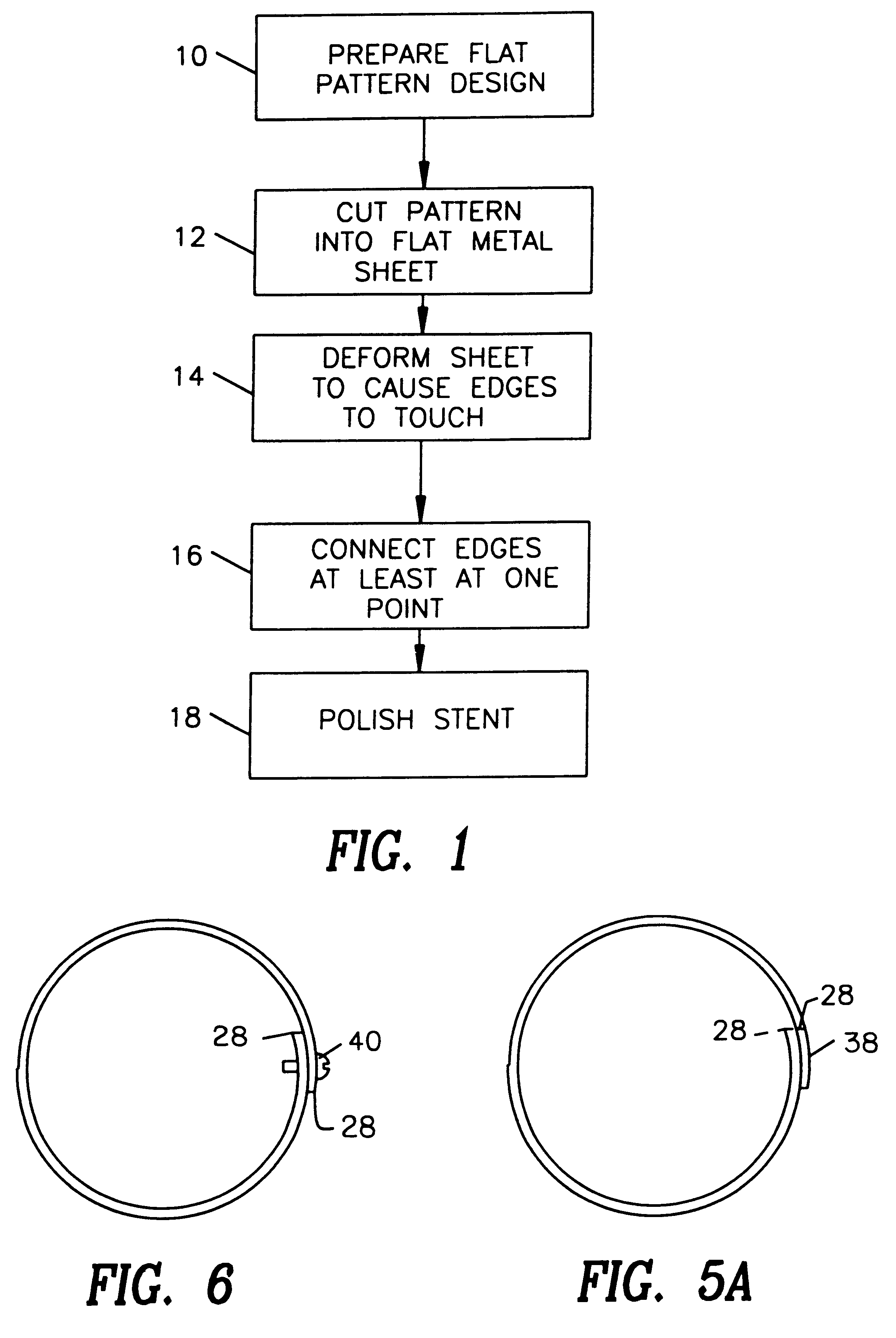
Reference is now made to FIG. 1, which illustrates the stent fabrication method of the present invention and to FIGS. 2A, 2B, 2C, 3 and 4 which are useful in understanding the method of FIG. 1.

In the stent fabrication method of the present invention, a stent designer first prepares a drawing of the desired stent pattern in a flat format (step 10).

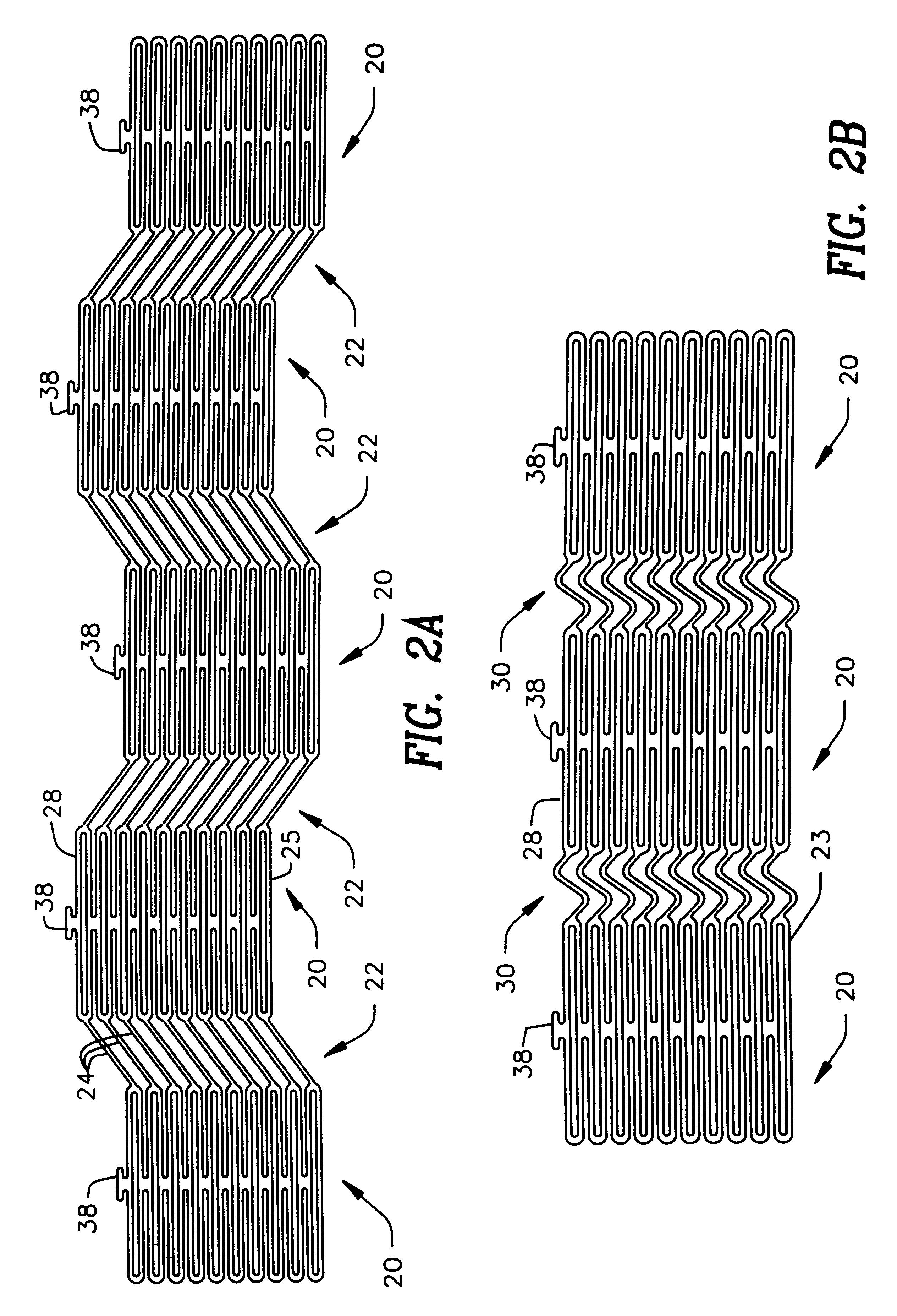
FIGS. 2A, 2B and 2C illustrate three exemplary stent pattern designs. The pattern of FIG. 2A has two types of sections 20 and 22. Each section 20 has two opposing periodic patterns and each section 22 has a plurality of connecting lines 24. The pattern of FIG. 2A can be formed of any size; a preferable size is to have each section 20 be between 1 and 6 mm wide and each section 22 have connecting lines 24 of 1-6 mm long. At such sizes, the pattern of FIG. 2A cannot be cut using a laser cutting system.

The pattern of FIG. 2B is similar to that of FIG. 2A in that it also has sections 20 of opposing periodic patterns. The pattern of FIG. 2B also...


PUM

PropertyMeasurementUnit
widthaaaaaaaaaa
sizeaaaaaaaaaa
sizeaaaaaaaaaa

Abstract

A stent and a method for fabricating the stent are disclosed. The stent has an originally flat pattern and connection points where the sides of the flat pattern are joined. The method includes the steps of a) cutting a stent pattern into a flat piece of metal thereby to produce a metal pattern, b) deforming the metal pattern so as to cause two opposing sides to meet, and c) joining the two opposing sides at least at one point. Substantially no portion of the stent projects into the lumen of the stent when the stent is expanded against the internal wall of a blood vessel.

Description

The present invention relates generally to methods of fabricating stents.Stents are known in the art. They are typically formed of a cylindrical metal mesh which can expand when pressure is internally applied. Alternatively, they can be formed of wire wrapped into a cylindrical shape.As described in U.S. Pat. No. 4,776,337 to Palmaz, the cylindrical metal mesh shape is produced by laser cutting a thin walled metal tube. The laser cuts away all but the lines and curves of the mesh.The method of U.S. '337 is applicable for relatively large mesh shapes and for meshes whose lines are relatively wide. However, for more delicate and / or intricate shapes, the spot size of the laser is too large.SUMMARY OF THE PRESENT INVENTIONIt is, therefore, an object of the present invention to provide a stent fabrication method which can produce stents with relatively intricate and / or delicate designs.The method involves first creating a flat version of the desired stent pattern from a piece of thin she...

Claims


Application Information

Patent Timeline
Patent Type & Authority Patents(United States)
IPC IPC(8): A61F2/06A61F2/82A61F2/90A61M29/02B21D51/16B23H3/00B23H9/00B23K26/10B23K26/22B23K37/04
CPCA61F2/91B21F45/008B23K26/083B23K26/10B23K26/12B23K26/22B23K26/38B23K33/006B23K37/053B23K26/127A61F2/915Y10T428/12229A61F2002/91541A61F2002/91558A61F2230/0054Y10T428/12188Y10T428/12201A61M29/00
Inventor RICHTER, JACOB
Owner MEDINOL LTD
Why Eureka
Try Eureka