Optical regeneration for optical-fiber transmission systems for non-soliton signals

Inactive Publication Date: 2001-03-13
ALCATEL LUCENT SAS
View PDF6 Cites 35 Cited by
  • Summary
  • Abstract
  • Description
  • Claims
  • Application Information

AI Technical Summary

Benefits of technology

It is possible to provide a clock recovery step whereby the clock is recovered from the non-sol

Problems solved by technology

One of the problems encountered, in particular for existing systems, is that of increasing the data rate or the transmission distance without giving rise to error.
That approach is limited by the jitter caused by the propagation and by the various optical components of the transmission system.
Similar problems are encountered for transmission systems using Non-Return-to-Zero (NRZ) pulses.
That approach is intrinsically limited by the pass-band of the semiconductor components used.
It is als

Method used


Image

  • Optical regeneration for optical-fiber transmission systems for non-soliton signals
  • Optical regeneration for optical-fiber transmission systems for non-soliton signals
  • Optical regeneration for optical-fiber transmission systems for non-soliton signals

Examples


first embodiment

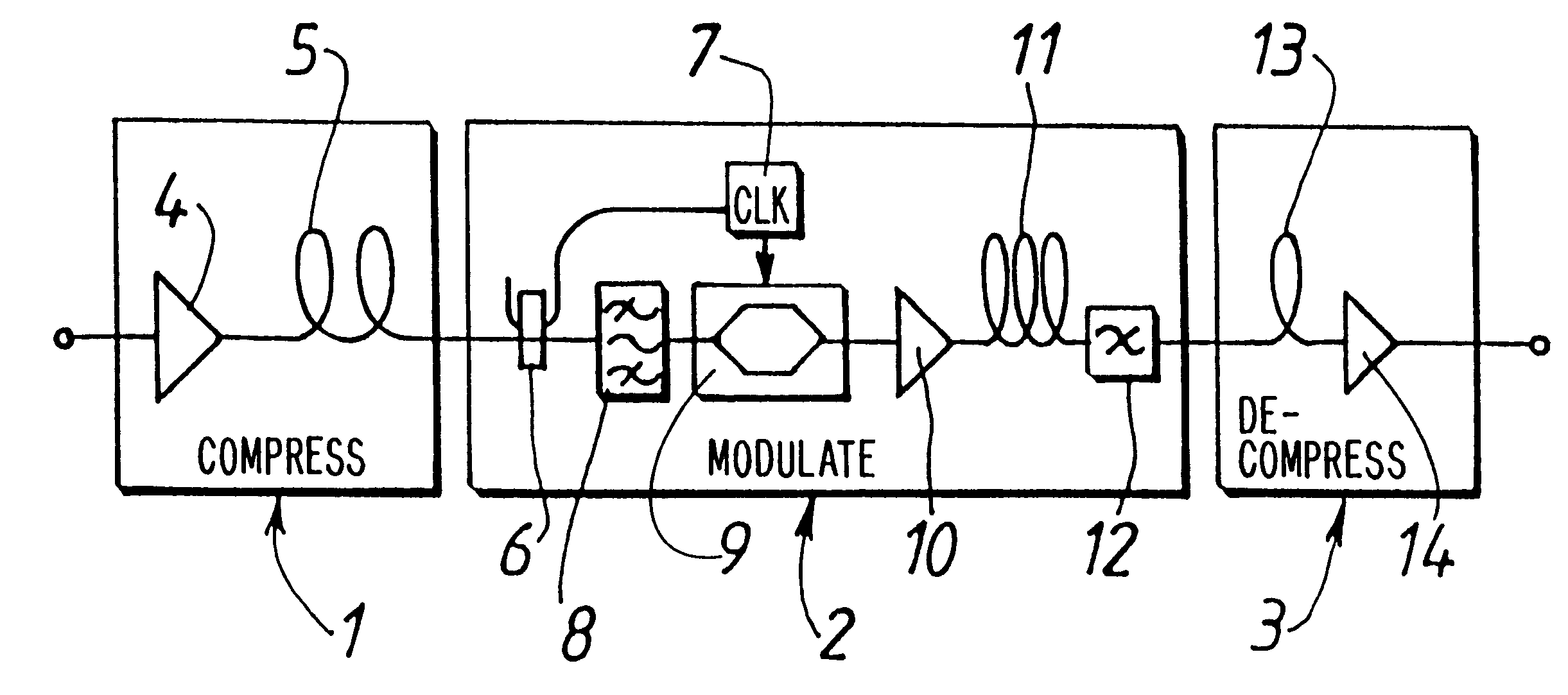
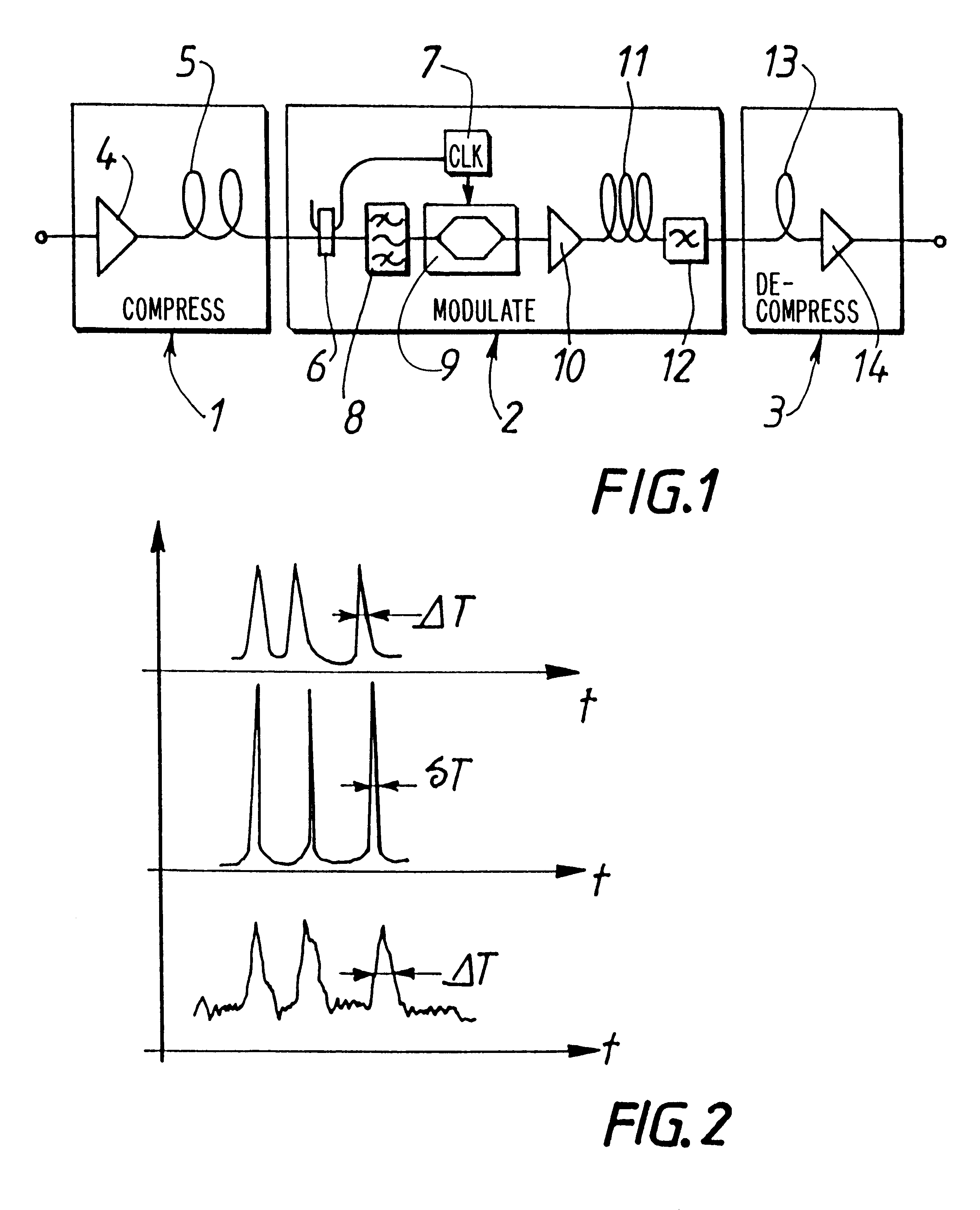
FIG. 1 is a diagram showing a regenerator of the invention. The FIG. 1 regenerator is designed to be used in an optical fiber transmission system for RZ signals, as in a commonly installed terrestrial system. The FIG. 1 regenerator comprises compression means 1 for compressing the RZ signals into soliton-type signals, modulation means 2 for performing synchronous optical modulation on the soliton-type signals, and decompression means 3 for decompressing the modulated soliton signals into non-soliton RZ signals.

The compression means 1 in the embodiment shown in FIG. 1 include a preamplifier 4 which receives the RZ optical signals to be regenerated. The outlet of the pre-amplifier 4 is connected to a compression fiber 5, e.g. a Kerr fiber having high dispersion. It is possible to vary the dispersion of the fiber as a function of distance so as to optimize the compression factor. The fiber delivers compressed signals which behave like soliton signals. It is possible to use some other c...

second embodiment

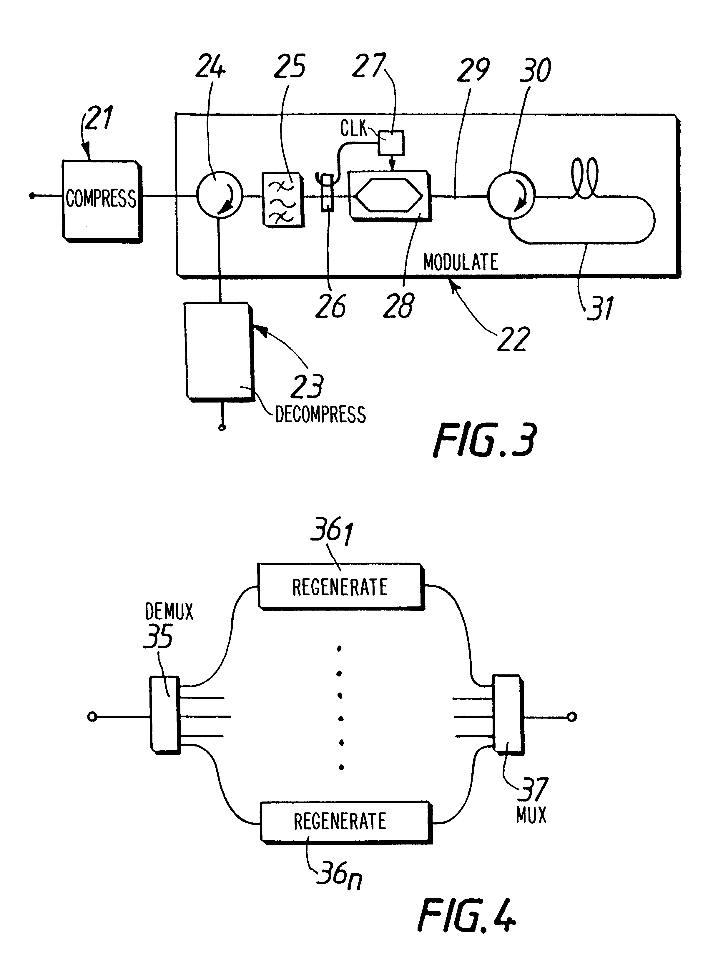
FIG. 3 is a diagram showing a regenerator of the invention. In this embodiment, the synchronous modulation is applied twice to the soliton-type signals, so as to reduce the amplitude noise. The amplitude noise is removed in part by the first synchronous modulation, because of the duty ratio of the modulation clock. The noise is dispersed during the propagation, and it is again removed in part by the second synchronous modulation, as explained in the above-mentioned passage from the article by H. Kubota.

Like the FIG. 1 regenerator, the regenerator shown in FIG. 3 comprises compression means 21, modulation means 22, and decompression means 23. The compression means 21 and the decompression means 23 are not described in any more detail. At their inlet, the modulation means include a three-port circulator 24 which receives the soliton-type signals to be modulated via a first port, and transmits them so that they are output via a second port. The signals to be modulated are delivered to ...

third embodiment

FIG. 4 is a diagram showing a regenerator of the invention that is suitable for multiplexed RZ signals. The FIG. 4 regenerator is suitable for the case when multiplexing is applied in the transmission system to the non-soliton RZ optical signals. It may be time division multiplexing (OTDM) or wavelength division multiplexing (WDM).

At its inlet, the regenerator shown in FIG. 4 includes demultiplexing means 35 for demultiplexing the multiplexed RZ optical signals, which demultiplexing means deliver the signals of the various channels at a plurality of outlets. It then includes a plurality of regenerators 36.sub.n to 36.sub.n, of the type described with reference to FIGS. 1 to 3, which regenerators apply synchronous modulation to the demultiplexed RZ signals. After the regenerators, the FIG. 4 circuit includes multiplexing means 37 for multiplexing the regenerated signals. It is clear to a person skilled in the art how the FIG. 4 regenerator operates. This regenerator makes it possible...


PUM


Abstract

A method of regenerating non-soliton RZ optical signals, the method including the steps of: a compression step, whereby the RZ signals are compressed into soliton-type signals; a modulation step whereby synchronous optical modulation is performed on the soliton-type signals, by using a clock; and a decompression step whereby the modulated soliton signals are decompressed into non-soliton RZ signals. The method makes it possible to apply soliton modulation techniques to non-soliton RZ links, so as to increase the data rate or the transmission length of such inks without inducing errors, and without having to modify the transmission medium. The invention also relates to a regenerator operating using the method. It is also possible to apply the method to NRZ signals, by converting them into RZ signals. The invention is also applicable to multiplexed RZ or NRZ signals.

Description

Transmitting Return-to-Zero (RZ) pulses is currently in common use in terrestrial optical-fiber transmission systems. One of the problems encountered, in particular for existing systems, is that of increasing the data rate or the transmission distance without giving rise to error. Various solutions have been proposed. A first approach consists in reducing the duration of the RZ pulses, and in using time-division multiplexing. That approach is limited by the jitter caused by the propagation and by the various optical components of the transmission system. Similar problems are encountered for transmission systems using Non-Return-to-Zero (NRZ) pulses.In order to mitigate that problem, it is known that the optical signal can be converted into an electronic signal in the regenerators and the electronic signal can then be regenerated. That approach is intrinsically limited by the pass-band of the semiconductor components used. It is also limited in terms of the maximum length of the tran...

Claims


Application Information

Patent Timeline
IPC IPC(8): H04B10/18H04B10/17H03M5/06H04B10/02H04J14/00H04J14/04H04J14/06
CPCH04B10/25077H04B10/299H04B2210/258
Inventor DESURVIRE, EMMANUELMAUNAND, ELISABETH
Owner ALCATEL LUCENT SAS
Why Eureka
Try Eureka