Dental magnetic attachment and its fixing method including spacer

a technology of dental magnetic attachment and fixing method, which is applied in the field of dental magnetic attachment and its fixing method including spacer, can solve the problems of insufficient concentrated concentration is apt to injure the abutment teeth, and inability to achieve enough vertical shrinkage for practical us

Inactive Publication Date: 2001-03-20
AICHI STEEL
View PDF10 Cites 36 Cited by
  • Summary
  • Abstract
  • Description
  • Claims
  • Application Information

AI Technical Summary

Problems solved by technology

However conventional types of dental magnetic attachment have a week point to give damage to an abutment tooth with a keeper when they are applied to dentures.
This concentration is apt to injure the abutment teeth.
This gap is apt to cause some trouble that something such as dregs of food is put into the gap and is rotten in it.
On the contrary when the cap of this type is designed to make the traverse extension to be small, vertical shrinking inevitably comes to be small.
In the case, enough vertical shrinking for practical use is not obtained.
The seesaw motion can solve the problem that denture is put out of the place due to leaning the denture But it does not show an enough cushion ability to the vertical pressure caused by biting force.
So it is concluded that this type gives not enough solution on the drawback of conventional types of magnetic attachment, especially when it is applied to free saddle denture.

Method used


Image

  • Dental magnetic attachment and its fixing method including spacer
  • Dental magnetic attachment and its fixing method including spacer
  • Dental magnetic attachment and its fixing method including spacer

Examples


first embodiment

(The construction of the first example of the magnetic attachment)

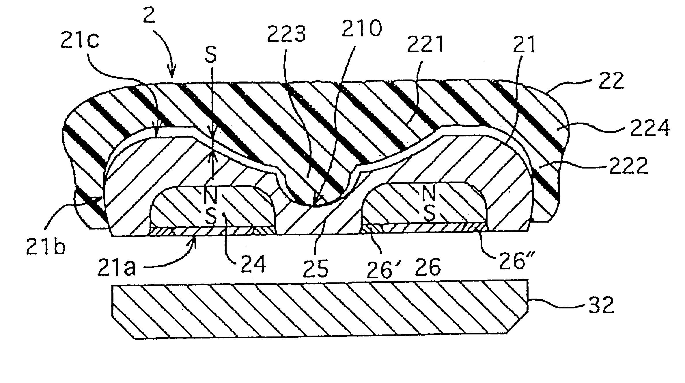
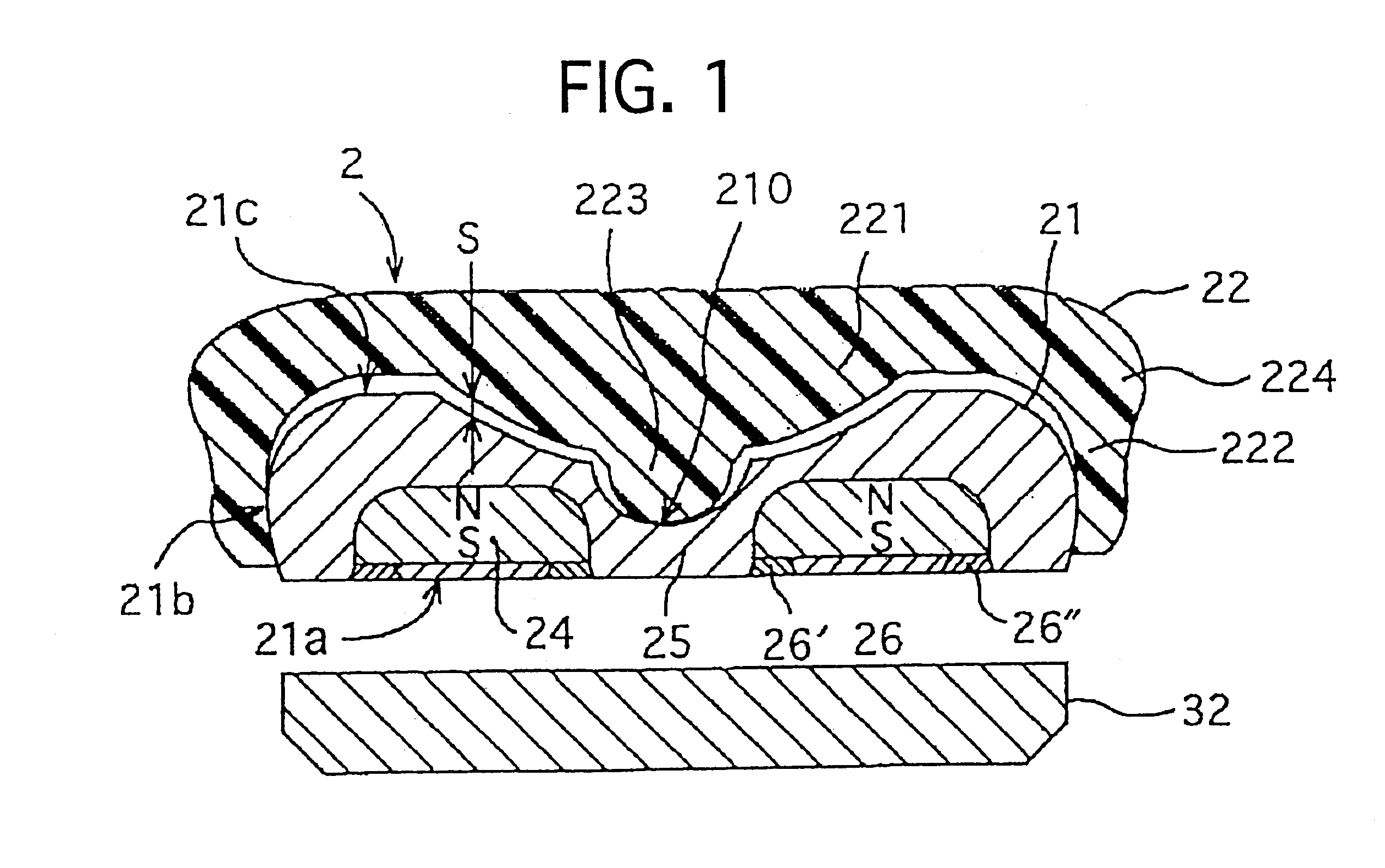
The first example as shown in FIG. 4 is comprised with a magnetic assembly 21, a keeper 3 and a cushion cap 22. The magnetic assembly is covered by the cap 22 on the top side of it and they are unified mechanically to one. They are put into the base 12 of the denture 1. The keeper 3 is put on the teeth root T. The magnetic assembly 2 and the keeper 3 is attracted with a magnetic force.

Here the magnetic assembly 21 is compromised with a ring shaped magnet 24, a cap yoke 25 showing a complicated shape and a disk yoke 26. The magnet 24 is surrounded by the cap yoke 25 and the disk yoke 26 in the manner that a hole of the magnet 24 is filled up by the cap yoke 25. They forms a magnetic circuit to connect the magnet 24 with the keeper 32 to make a strong attractive force. Here it is important to insulate the disk yoke 26 from the cap yoke 25 magnetically. The inner sealing ring 26' and the outer sealing ring 26" are parts ...

second embodiment

FIG. 8 shows a cross section of the second example of the magnetic attachment in which a helper cushion 4 made of foaming material such as foaming rubber and urethane foam is inserted into the gap between the magnetic assembly 21 and the cap 22.

The helper cushion makes the effect to prevent some alien substance from entering the gap without reducing the cushion property.

third embodiment

FIG. 9 shows a cross section of the third example same to the second example except the following points. One is that the helper cushion 4' is made of elastic rubber such as silicon rubber. The second point is that the gap between the magnetic assembly 21 and the cap 22 is filled up partially by the helper cushion 4'.

The helper cushion makes the same effect to the second example and in addition, to reduce the impact by elastic compression when the cap 22 collides against the top of the magnetic assembly 21.


PUM


Abstract

A dental magnetic attachment having good cushioning properties against a compressing pressure which makes a denture sink appropriately on biting. The dental magnetic attachment embedded in the denture base for holding the denture in the oral cavity by a magnetic attractive force working with the magnetic assembly and a soft magnetic keeper embedded in the top of the root surface includes a magnetic assembly and a cap covering the top of the magnetic assembly. The magnetic assembly has a hollow in the center of its top. The cap with a button is placed on the magnetic assembly, inserting the button into the hollow to contact to its bottom. On biting, the button is compressed, to be deformed with a shorter thickness and at this time a sleeve formed as a body around the core slides down along the side of the magnetic assembly to reduce the thickness of the dental magnetic attachment. This sliding makes the denture sink uniformly and appropriately. The dental magnetic attachment has good cushioning properties and offers a good feeling to a patient when biting with the denture.

Description

The present invention relates to a dental magnetic attachment which is embedded in a denture to stabilize the denture on abutment teeth in the oral cavity using magnetic attractive force.DESCRIPTION OF THE PRIOR ARTUp to the present, a dental magnetic attachment which strongly stabilize the denture on abutment teeth by magnetic attractive force is well known. Its force is acted between a magnetic assembly in a denture and a keeper made from a soft magnetic material embedded in a root cap.However conventional types of dental magnetic attachment have a week point to give damage to an abutment tooth with a keeper when they are applied to dentures. Each biting makes nearly equal pressure to any artificial teeth of the denture. In the case of free saddle denture shown as FIG. 22, the parts on the abutment tooth marked as A shows only small sinking depth of about 0.02 mm, on the other hand the parts on gingiva marked as B shows large scale sinking depth of about 0.2 mm. It means that the ...

Claims


Application Information

Patent Timeline
Patent Type & Authority Patents(United States)
IPC IPC(8): A61C13/225A61C13/235
CPCA61C13/235
Inventor HONKURA, YOSHINOBUARAI, KAZUOKIMURA, KAZUNARI
Owner AICHI STEEL
Why Eureka
Try Eureka