Method of pipe welding

a pipe welding and pipe technology, applied in the direction of soldering equipment, instruments, manufacturing tools, etc., to achieve the effect of improving flow characteristics, excellent appearance, and high travel speed

Inactive Publication Date: 2001-03-20
LINCOLN GLOBAL INC
View PDF5 Cites 61 Cited by
  • Summary
  • Abstract
  • Description
  • Claims
  • Application Information

AI Technical Summary

Benefits of technology

After substantial experimentation and costly investigation it has been found that a quality weld is produced consistently with an excellent appearance and highest travel speed because of better flow characteristics when phosphorous is maintained at only a trace and sulfur is maintained at a high level in the specific range of over 0.015% by weight and less than 0.035% by weight in the welding wire. By controlling and maintaining these limits for phosphorous and sulfur in the welding wire, a consistent good appearing open root weld is accomplished. Consequently, in accordance with the present invention there is provided a method of welding the ends of two pipes at the gap or open root between the spaced ends. This method comprises selecting a welding wire having 0.06-0.15% by weight of carbon, 0.90-1.40% by weight manganese, and 0.45-0.75% by weight silicon. In addition, the wire includes phosphorous, copper, stainless steel alloys and sulfur. The method involves maintaining the sulfur at a given percentage level of the selected wire in the specific range of 0.015 -0.35% by weight and maintaining the phosphorous at a given percentage level of the selected wire in the specific range of less than about 0.015%. Indeed, the phosphorous is normally at a trace or tramp level of 0.006-0.008% by weight of the welding wire. In this invention, the selected welding wire is advanced at a given wire feed rate toward the open root between the spaced pipe ends to weld the sections together by filling the open root in a first weld pass, creating a welding current with a controlled wave form, which wave form includes a succession of welding cycles each having a short circuit portion and a plasma arc portion with the plasma arc portion including in sequence a plasma boost segment, a tailout segment and a background current segment. The welding wire is moved along the open root as the welding current is passed through the wire to melt the wire and transfer the wire by surface tension transfer to the pipe ends thereby filling the open root. The current wave form is formed by a rapid succession of current pulses created by an oscillator at a rate of at least 18 kHz and with a width controlled by a pulse width modulator. By using the invention, a high quality weld bead is deposited in the open root during the first pass of a welding process. Thereafter, another welding wire, such as a flux cored wire can be used to fill the remainder of the joint. Thus, the root pass is filled by an optimized weld procedure and the remaining joint is filled by a procedure tailored to high deposition demands.

Problems solved by technology

It has been found that a cored electrode has substantial advantages when used with an STT electric arc welder in welding the joint between pipe sections; however, the open root pass weld bead presents unique welding challenges.

Method used


Image

  • Method of pipe welding
  • Method of pipe welding
  • Method of pipe welding

Examples


Embodiment Construction

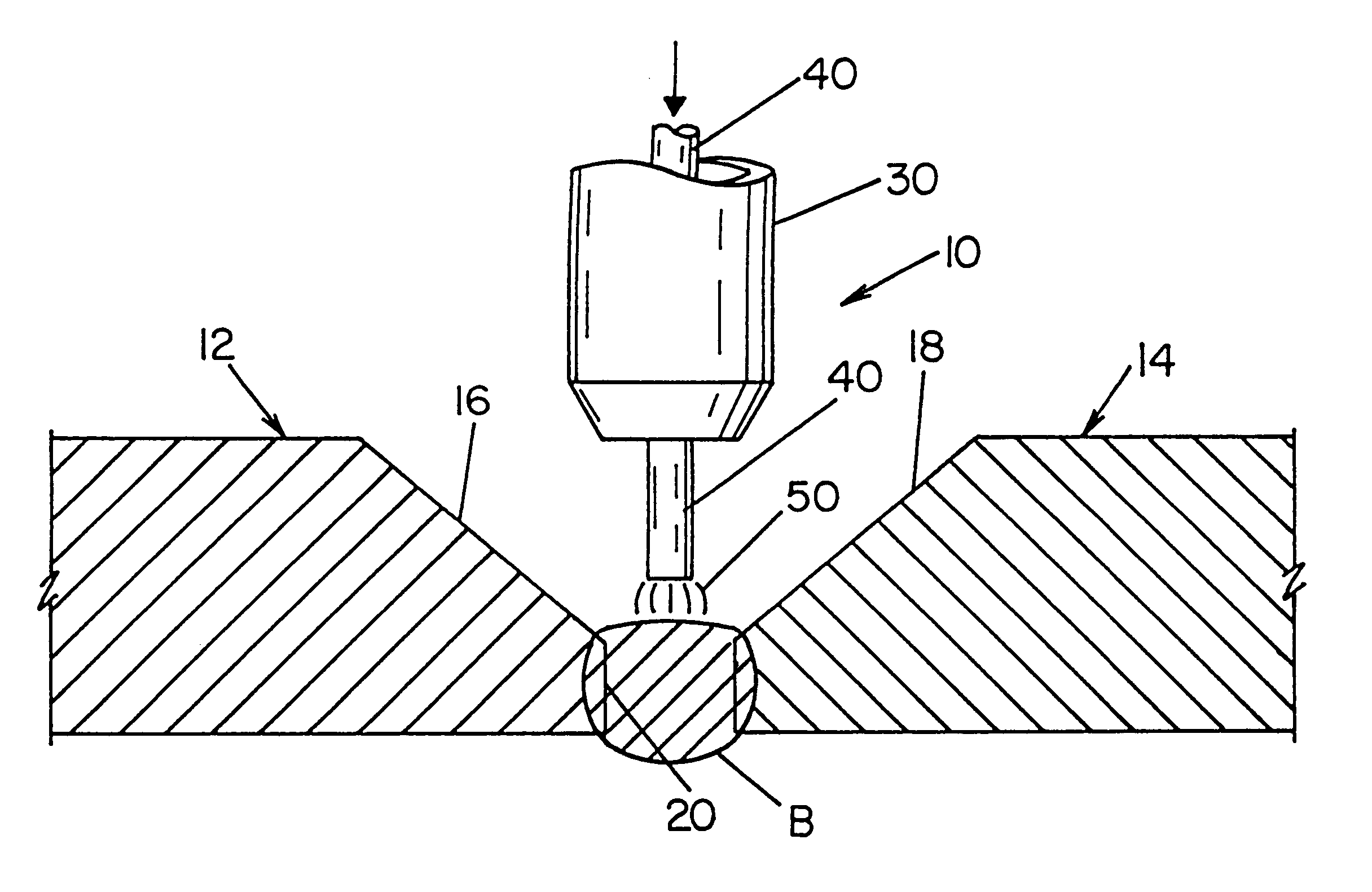
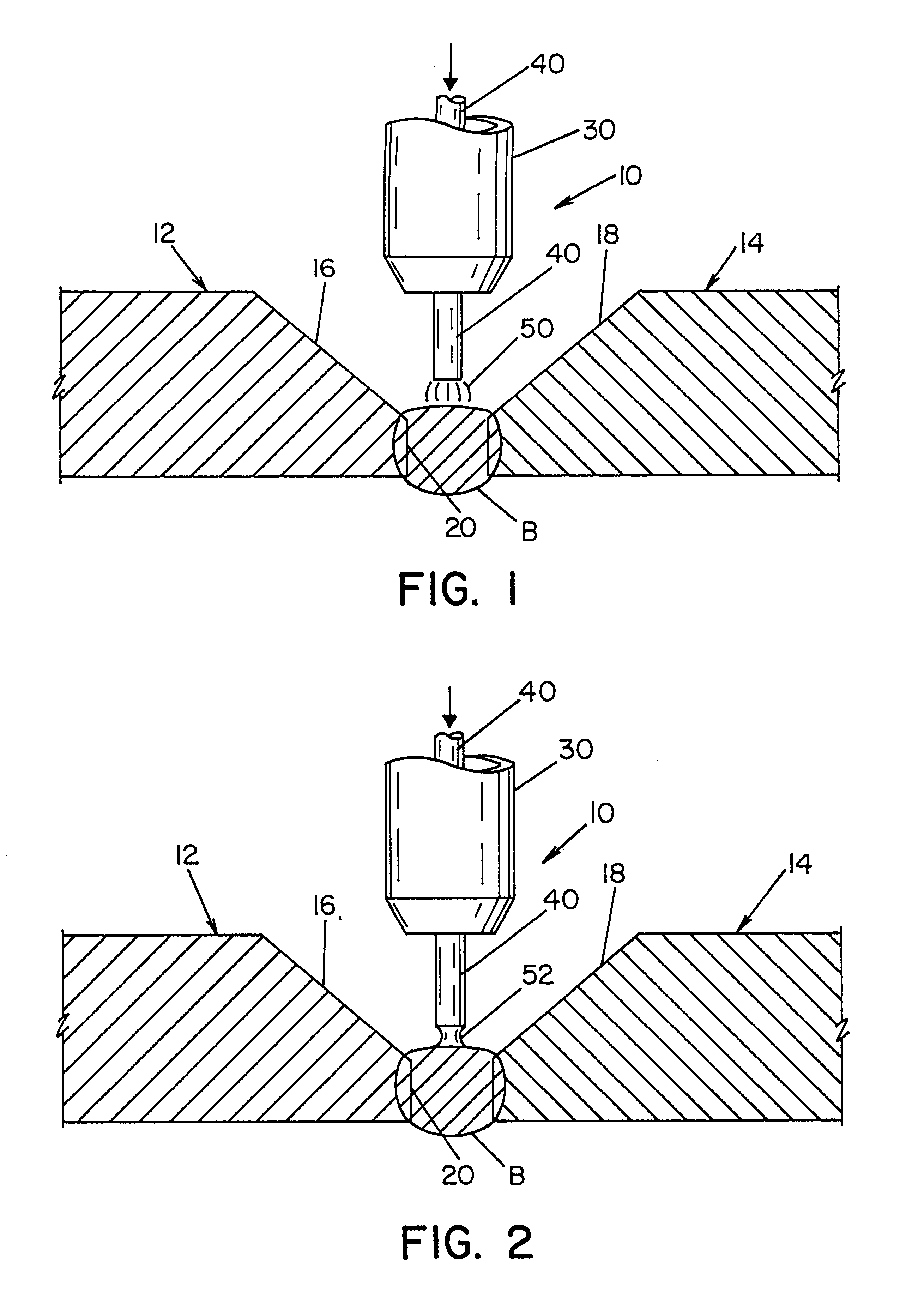
The present invention relates to a method of welding the ends of two pipes at the open root between the ends by using a special welding wire in combination with the STT welding procedure. In FIGS. 1 and 2 the pipe welding operation 10 is used to weld the pipe sections 12, 14 having a gap or open root 20 defined by tapered ends 16, 18, which ends are spaced apart in accordance with standard practice. The invention relates to the laying or deposition of the first weld bead B in the open root 20 by moving torch 30 around the pipe sections 12, 14 while the torch follows a path determined by the joint including root pass 20 at the bottom. In accordance with the invention, a wire 40 is fed at a selected rate through torch 30 toward root pass 20 while welding current is passed through the welding wire. The welding current creates an arc 50 as shown in FIG. 1 to melt the end of the advancing wire 40. As the wire is converted to a molten ball and moved toward bead B, a short circuit conditio...


PUM

PropertyMeasurementUnit
weight percentaaaaaaaaaa

Abstract

A method of welding the ends of two pipes at the open root between the spaced ends by an STT electric arc welder, which comprises: selecting a welding wire having 0.06-0.15% by weight carbon, 0.90-1.40% by weight manganese, and 0.45-0.75% by weight silicon, as well as phosphorous, copper, stainless steel alloys and sulfur; maintaining the sulfur at a given percentage level of the selected wire in the specific range of 0.015 to 0.035% by weight; and maintaining said phosphorous at a given percentage level of said selected wire in the specific range of less than about 0.015%.

Description

The present invention relates to a method of pipe welding and more particularly the method of using a particular welding wire with a specific power supply known in the pipe welding industry as the STT electric arc welder for welding the open root between pipe ends.INCORPORATION BY REFERENCEOver the last decade, the art of welding large plates together has adopted a short circuit electric arc welder for many specific welding applications. This welder sold by The Lincoln Electric Company of Cleveland, Ohio under the trademark STT is disclosed in Stava U.S. Pat. No. 5,742,029 for use in a specific wallpapering application. The unique short circuit electric arc welder is now the power supply of choice for electric arc welding of the spaced ends of pipe sections when laying pipe lines in the field. The implementation of a pipe welding method utilizing the unique short circuit welder is disclosed in Parker U.S. Pat. No. 5,676,857. Since these two patents and the material disclosed therein...

Claims


Application Information

Patent Timeline
Patent Type & Authority Patents(United States)
IPC IPC(8): B23K35/30B23K9/028B23K9/10B23K31/02B23K9/073B23K9/133B23K101/06
CPCB23K9/0282B23K9/1056B23K35/3053B23K2201/06B23K2101/06B23K9/133
Inventor NICHOLSON, PETERSTAVA, ELLIOTT K.
Owner LINCOLN GLOBAL INC
Why Eureka
Try Eureka