DC-to-DC converter capable of preventing overvoltage
a converter and dc technology, applied in the direction of electric variable regulation, process and machine control, instruments, etc., can solve the problems of increased output voltage, fire and smoke explosion, deterioration of dc/dc converter conversion efficiency,
- Summary
- Abstract
- Description
- Claims
- Application Information
AI Technical Summary
Benefits of technology
Problems solved by technology
Method used
Image
Examples
first embodiment
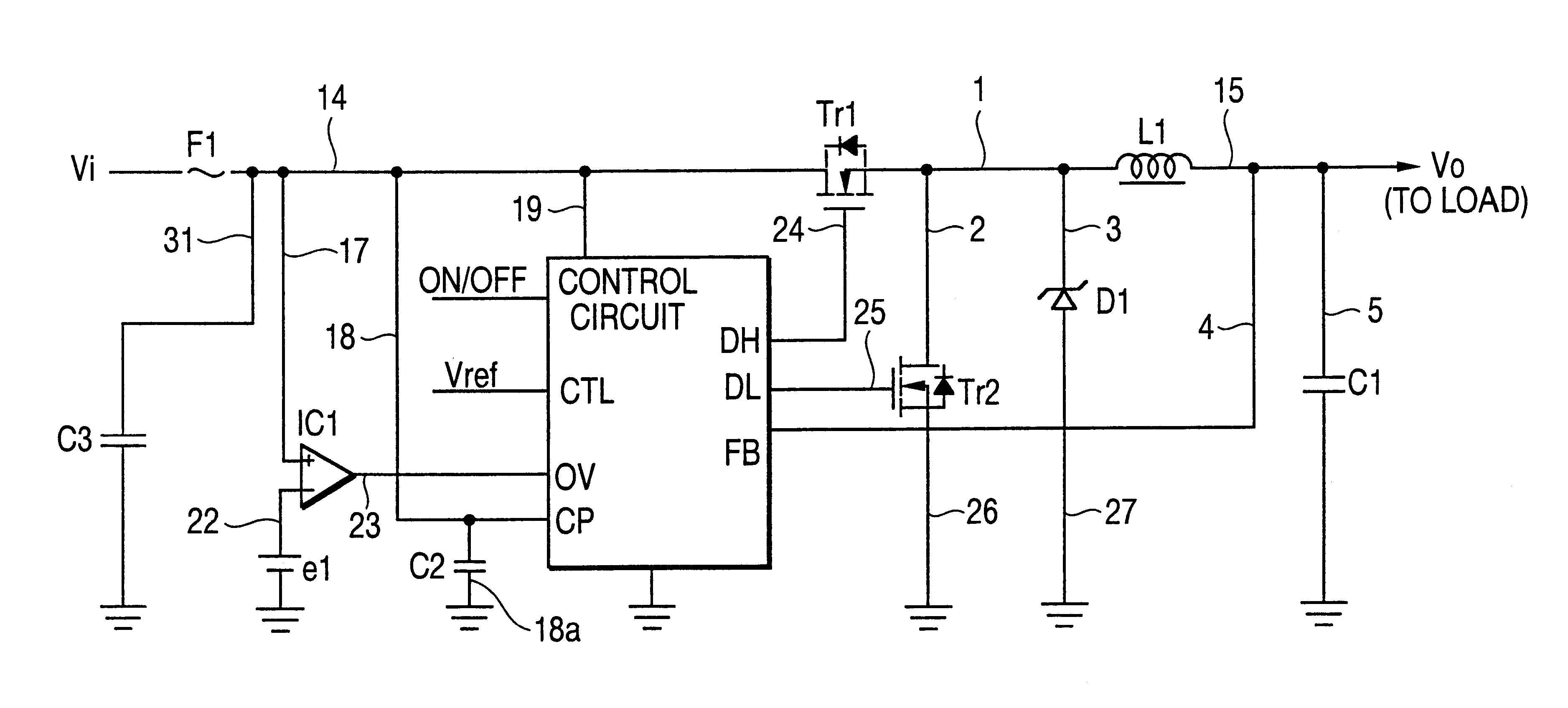
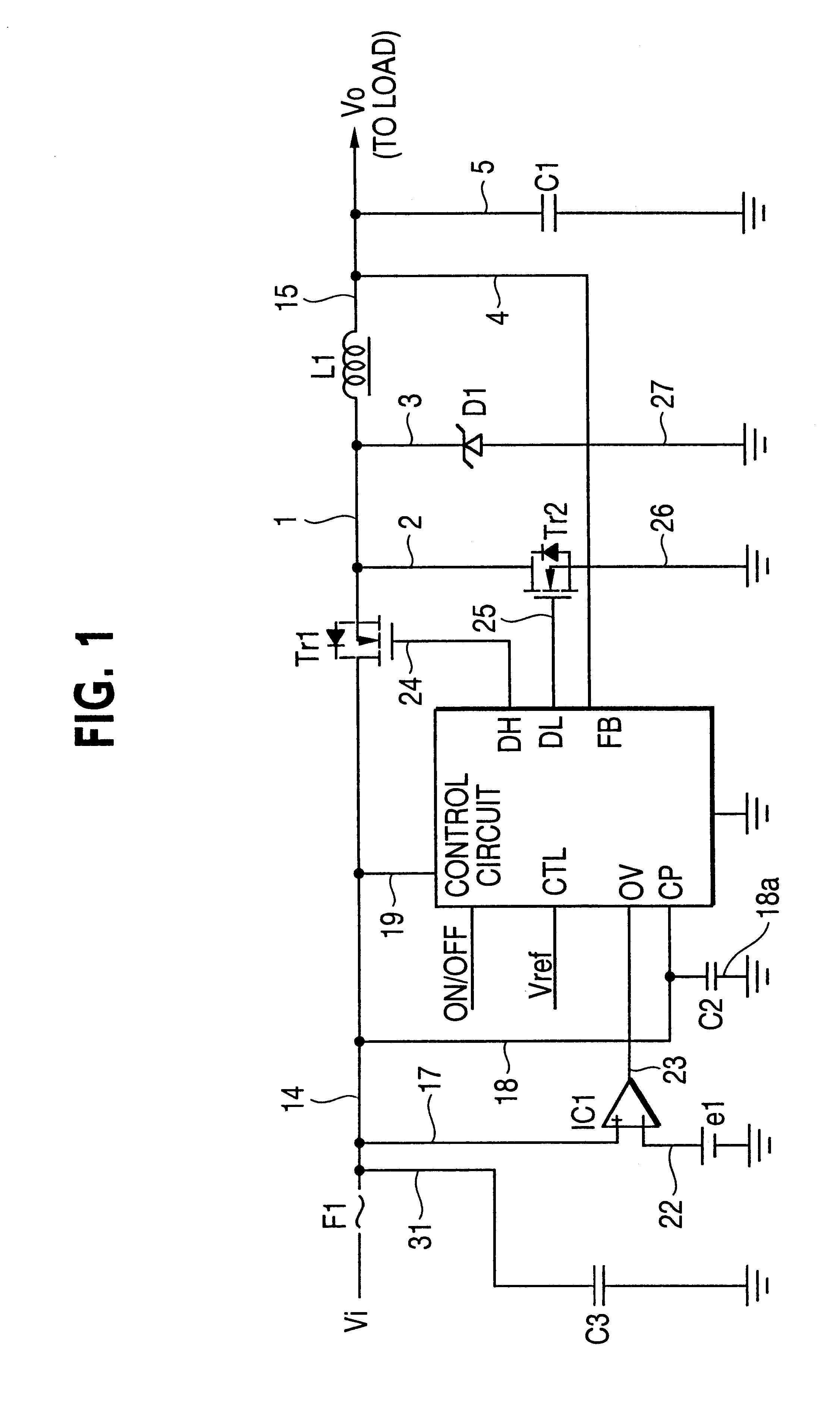
FIG. 1 is a schematic diagram for showing a DC-to-DC converter mode 1 of the present invention. It should be noted that the same reference numerals used in the prior art DC / DC converter will be employed as those for denoting the same or similar constructive elements in the following embodiment modes.
A DC / DC converter is provided between a cell functioning as a power supply and a load (not shown in FIG. 1), and is such an apparatus for converting a voltage applied from the cell into a constant voltage so as to supply this constant voltage to the load.
ARRANGEMENT OF FIRST DC / DC CONVERTER
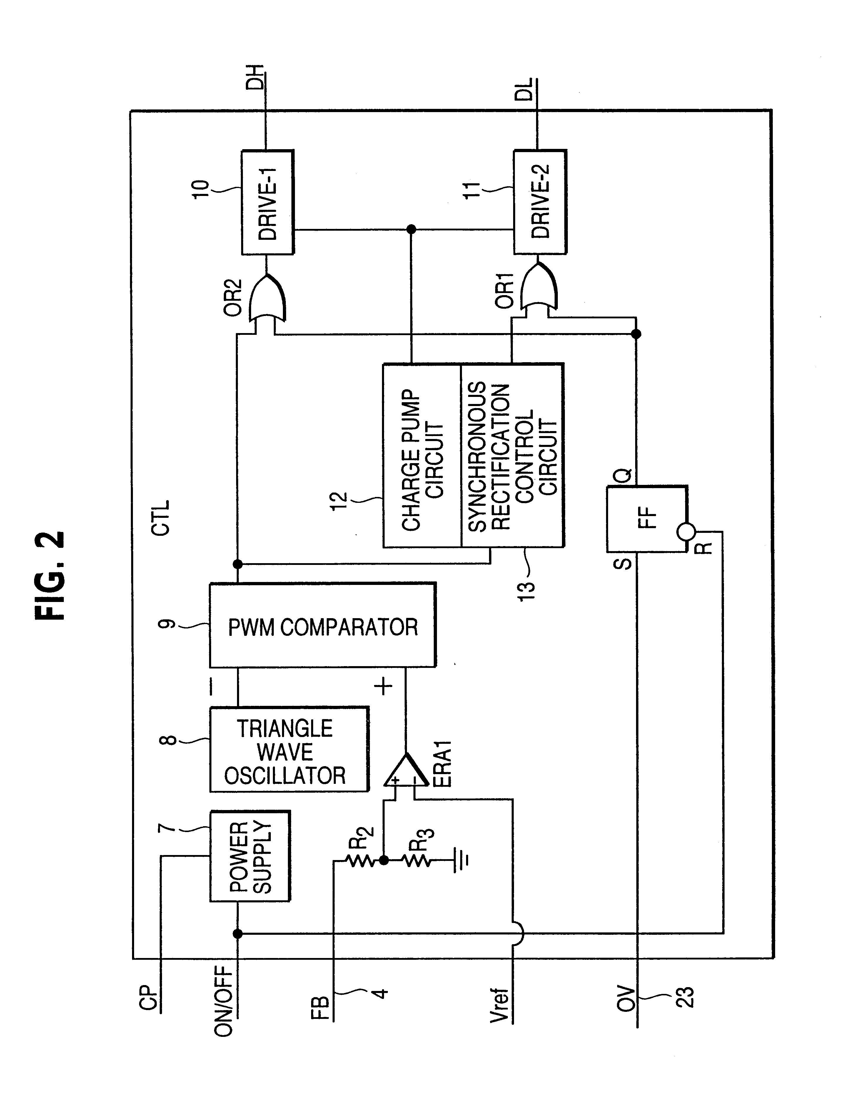
The DC / DC converter according to this embodiment mode 1 is constructed of a fuse F1, a control circuit CTL, a main switching transistor Tr1, a synchronous rectification transistor Tr2, a diode D1, a choke coil L1, a capacitor C1, a voltage comparator IC1, a power supply e1 for producing a reference voltage e1, a capacitor C2, and a capacitor C3.
(CIRCUIT CONNECTIONS FOR FIRST DC / DC CONVERTER)
Now, conne...
embodiment mode 2
FIG. 2 is a schematic diagram for showing a DC-to-DC converter according to a second embodiment mode 2 of the present invention. It should be noted that the same reference numerals used in the first DC / DC converter will be employed as those for denoting the same or similar constructive elements in the following embodiment modes.
A DC / DC converter is provided between a cell functioning as a power supply and a load.
(ARRANGEMENT OF SECOND DC / DC CONVERTER)
The DC / DC converter according to this embodiment mode 2 is constructed of, a control circuit CTL, a main switching transistor Tr1, a synchronous rectification transistor Tr2, a diode D1, a choke coil L1, a capacitor C1, a voltage comparator IC2, and a power supply e3 for producing a reference voltage e3.
(CIRCUIT CONNECTIONS FOR SECOND DC / DC CONVERTER)
Now, connection modes of the above-described constructive elements will be described.
The main switching transistor Tr1 is connected via a signal line 14 to a cell. This main switching trans...
embodiment mode 3
FIG. 9 is a schematic diagram for showing a DC-to-DC converter according to a third embodiment mode 3 of the present invention. It should be noted that the same reference numerals used in the above-described embodiment modes 1 and 2 will be employed as those for denoting the same or similar constructive elements in the following embodiment mode.
ARRANGEMENT OF THIRD DC / DC CONVERTER
The DC / DC converter is constructed of a fuse F1, a voltage comparator IC1, power supply e1, capacitor C3, capacitor C2, an OR gate circuit OR3, a control circuit CTL, a main switching transistor Tr1, a synchronous rectification transistor Tr2, a diode D1, a choke coil L1, a resistor R1a, capacitor C1, a voltage comparator IC2, and a power supply e3.
CIRCUIT CONNECTIONS FOR THIRD DC / DC CONVERTER
Now, connection modes of the above-described constructive elements will be described.
The fuse F1 is employed in a half way of a signal line 14 used to connect the cell with the main switching transistor Tr1.
The main sw...
PUM
 Abstract
Description
Claims
Application Information
 - R&D
- Intellectual Property
- Life Sciences
- Materials
- Tech Scout
- Unparalleled Data Quality
- Higher Quality Content
- 60% Fewer Hallucinations
Browse by: Latest US Patents, China's latest patents, Technical Efficacy Thesaurus, Application Domain, Technology Topic, Popular Technical Reports.
© 2025 PatSnap. All rights reserved.Legal|Privacy policy|Modern Slavery Act Transparency Statement|Sitemap|About US| Contact US: help@patsnap.com


