Noncontact laser microsurgical method

a non-contact laser and microsurgical technology, applied in the field of microsurgical equipment, can solve the problems of corneal strain, postoperative astigmatism, corneal refractive error, etc., and achieve the effect of eliminating the need for sutures and reducing astigmatism and/or corneal refractive error

Inactive Publication Date: 2001-04-03
UNIV OF MIAMI
View PDF7 Cites 54 Cited by
  • Summary
  • Abstract
  • Description
  • Claims
  • Application Information

AI Technical Summary

Benefits of technology

The present invention also provides a microsurgical method for ablating the cornea in selected areas by appropriate use of the disclosed apparatus. Moreover, by careful selection of the laser generating means the corneal tissue may be heated only sufficiently to cause shrinkage of the tissue in selected areas to alleviate astigmatism and / or corneal refractive error. Furthermore, by appropriate control of the selected laser generating means donor and recipient corneal tissue may be heated in abutting areas to cause the disparate tissue to adhere to one another in the manner of a surgical weld to thereby eliminate the need for sutures.

Problems solved by technology

However, such mechanical marking apparatuses directly contact and distort the cornea such that the marking process is not always precisely accomplished and sometimes results in porstkeratoplasty astigmatism.
This surgical method is apt to cause strain and / or deformation of the cornea, and also results in postoperative astigmatism.
Moreover, changing the focusing lens requires a time consuming process for each patient or donor.

Method used


Image

  • Noncontact laser microsurgical method
  • Noncontact laser microsurgical method
  • Noncontact laser microsurgical method

Examples


first embodiment

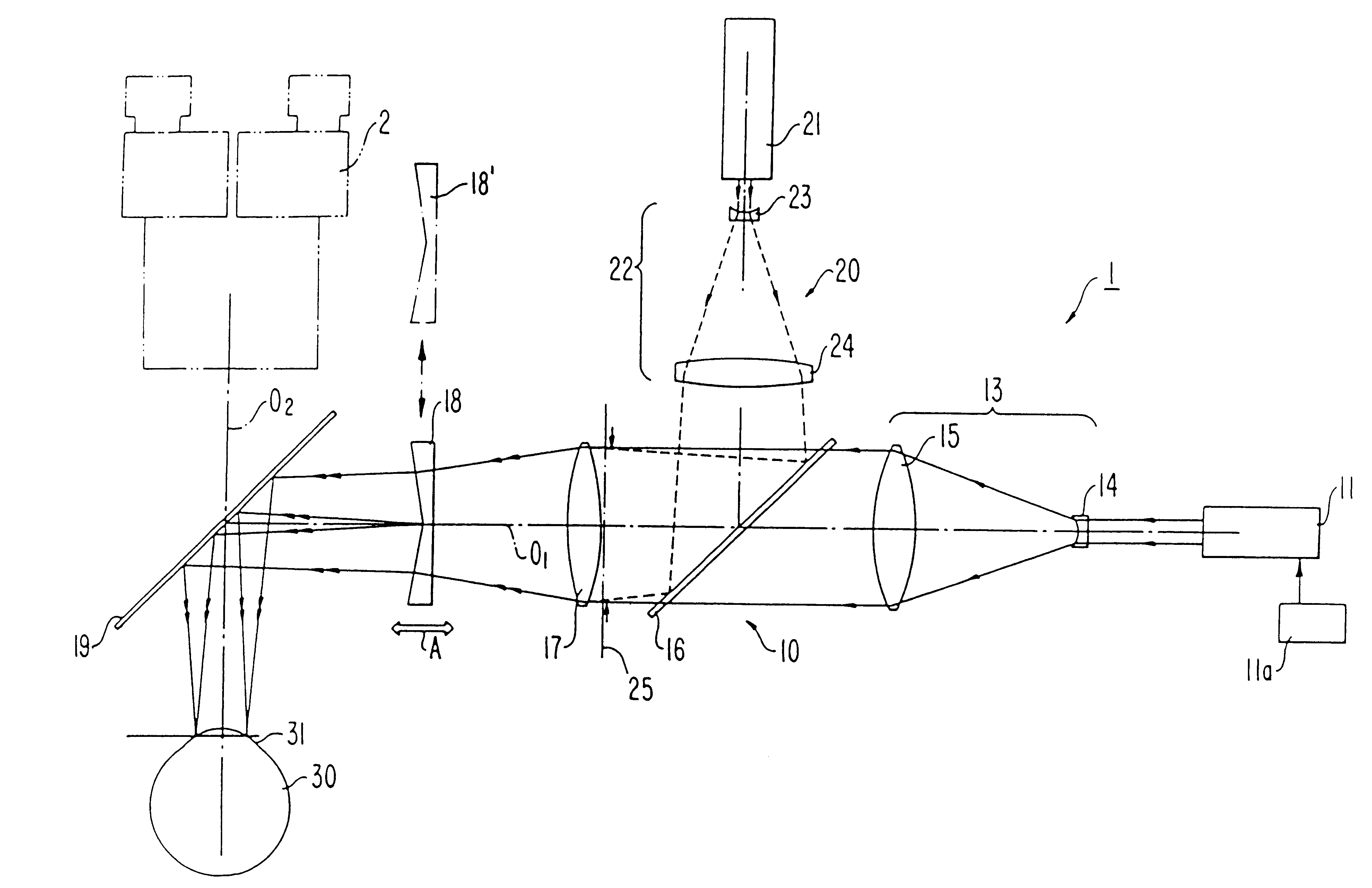
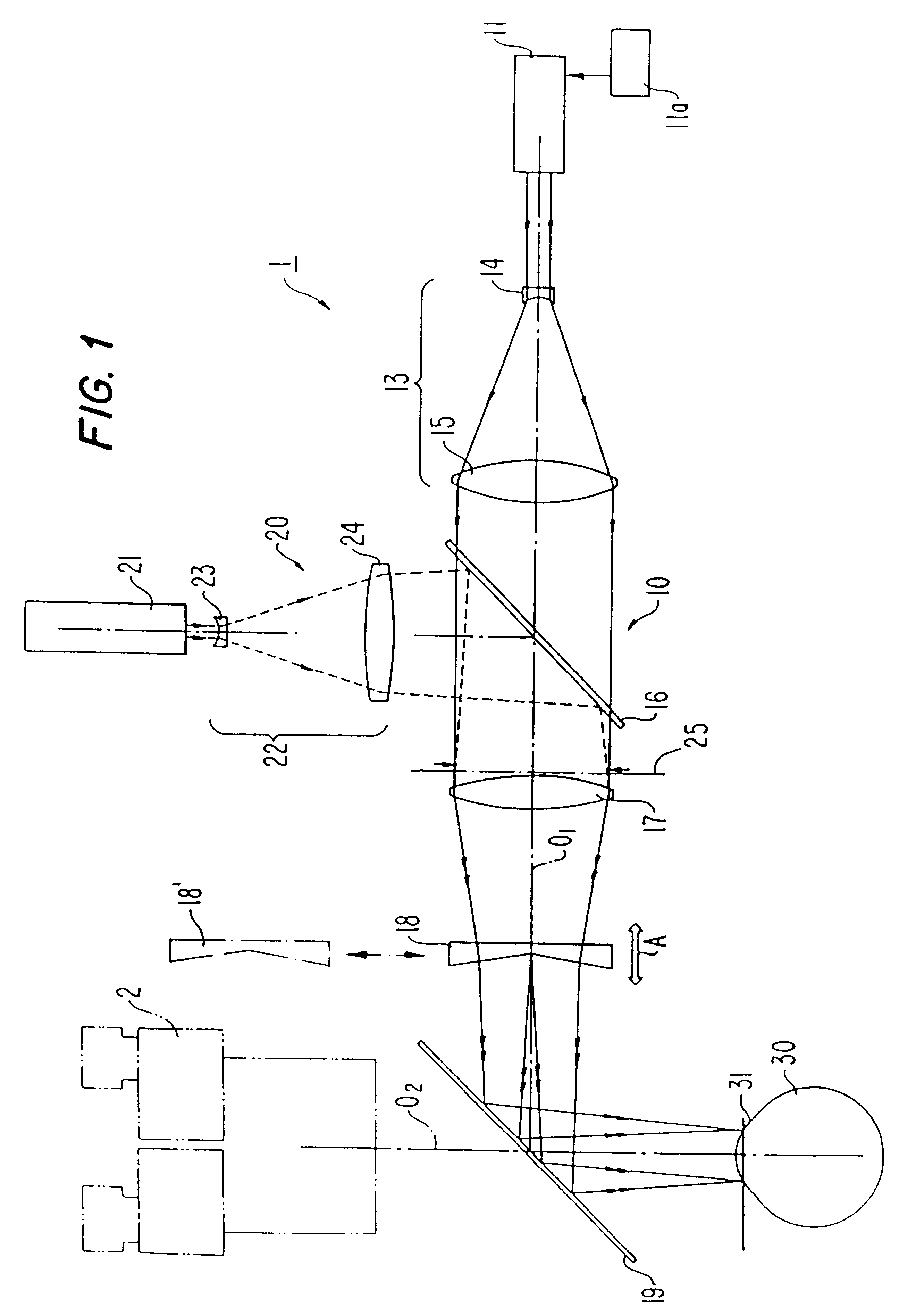
In accordance with the present invention, the apparatus includes axicon optical means for forming the converged laser beams into a plurality of paraxially distributed beam spots on the cornea. As embodied herein the axicon optical means may comprise a multiple-facet prismatic ("MFP") lens 18.

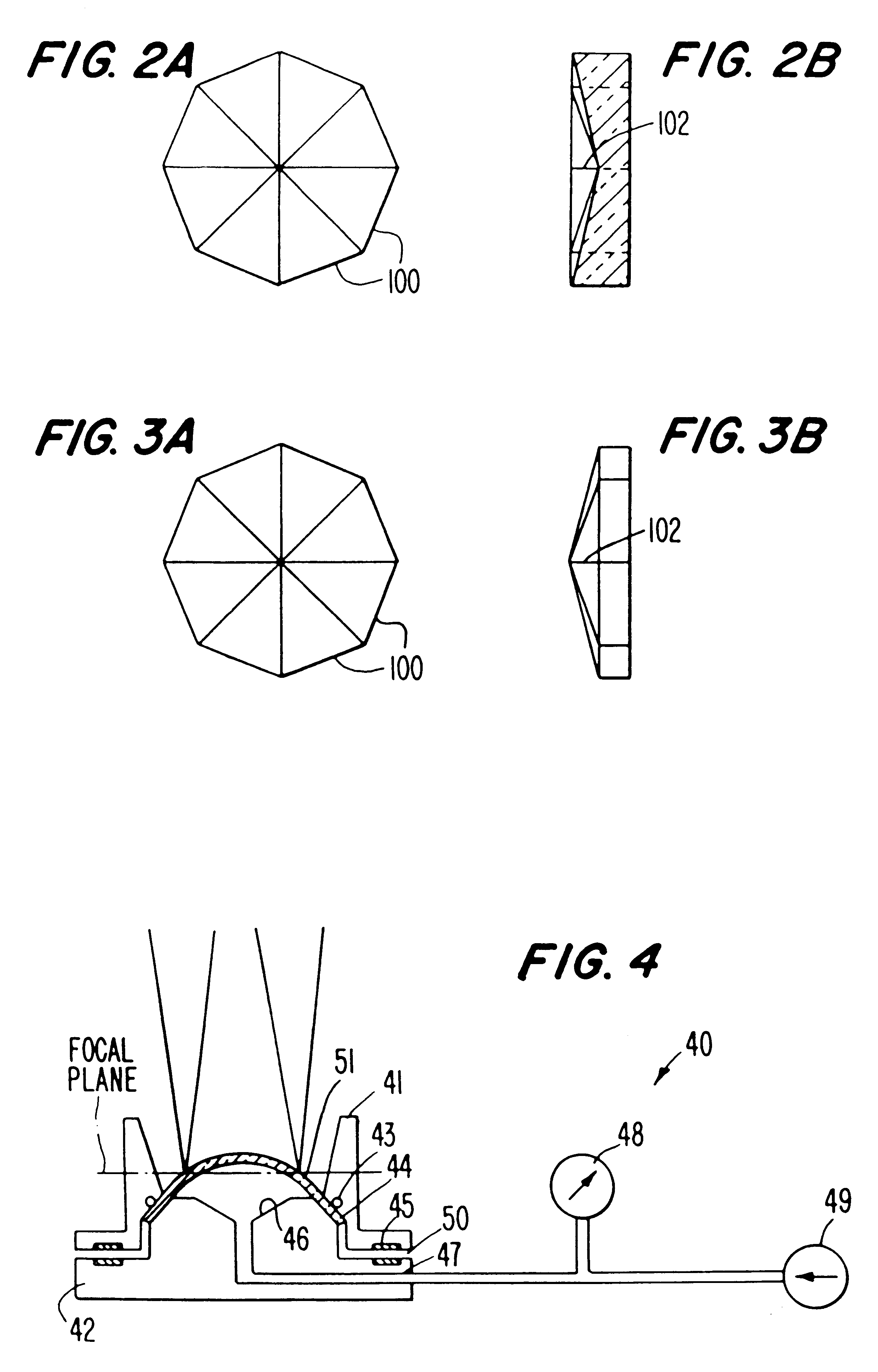
As shown in FIGS. 2A and 2B, axicon lens 18 may be configured with concave multiple-facet prisms (eight-facet prisms, for example) whose outer edges (prism bases) 100 are larger in width than the optical axis portion 102 thereof. Axicon lens 18 may also be configured with convex multiple-facet prismatic lenses as shown in FIGS. 3A and 3B whose outer edges (prism bases) 100 are larger in width than optical axis portions 102 thereof. With reference to FIG. 6, the multiple-facet prism function of axicon lens 18 causes the converging laser beams emerging from lens 18 to be formed into a plurality of paraxially distributed beam spots 61 on cornea 31 of eye 30. The spots 61 are radially spaced from th...

second embodiment

In the present invention, a conical axicon lens 18 illustrated with the dot-dash line in FIG. 1 may used in place of MFP axicon lens 18. In such an embodiment the conical axicon lens need not be rotated about optical axis O.sub.1 to perform curved keratotomy because the conical axicon lens converts the laser beams exiting from condensing and focusing lens 17 into annular beams and projects them toward the patient's cornea.

Each of FIGS. 15 and 16 illustrate alternative embodiments of the mask means. In both alternative embodiments of the mask means, two masks are spaced from one another on optical axis O.sub.1. Each mask is identical in configuration. Therefore, only one of the masks, mask 130, is illustrated in FIGS. 15 and 16.

By way of example and not limitation, mask 130 may comprise a metal plate having two fan-shaped opaque portions 132 and 134, and side edges 136 and 138 which are formed in a concave arc as shown in FIG. 15, or in a convex arc as shown in FIG. 16. Sinces the en...


PUM


Abstract

A noncontact laser microsurgical apparatus and method for marking a cornea of a patient's or donor's eye in transplanting surgery or keratoplasty, and in incising or excising the corneal tissue in keratotomy, and for tissue welding and for thermokeratoplasty. The noncontact laser microsurgical apparatus comprises a laser source and a projection optical system for converting laser beams emitted from the laser source into coaxially distributed beam spots on the cornea. The apparatus further includes a multiple-facet prismatic axicon lens system movably mounted for varying the distribution of the beam spots on the cornea. In a further embodiment of the method of the present invention, an adjustable mask pattern is inserted in the optical path of the laser source to selectively block certain portions of the laser beams to thereby impinge only selected areas of the cornea.

Description

1. Field of the InventionThe present invention relates to a microsurgical apparatus and, more particularly, a noncontact laser microsurgical apparatus adapted for use in cornea transplant surgery, keratoplasty, keratotomy, and other corneal surgery techniques.2. Description of the Related ArtDespite advances in corneal preservation and transplantation techniques, postoperative astigmatism remains the most important complication limiting visual acuity after a corneal transplantation.In order to reduce such postoperative astigmatism, U.S. patent application Ser. No. 07 / 056,711 filed Jun. 2, 1987 entitled "A Cornea Laser-Cutting Apparatus", assigned to the same assignee as the present application, discloses that trephination of either a donor cornea or a recipient cornea may be performed utilizing a laser cutting technique.During penetrating keratoplasty, it is further necessary for a surgeon to align the circumferences of the donor corneal button and recipient cornea. To this end, the...

Claims


Application Information

Patent Timeline
Patent Type & Authority Patents(United States)
IPC IPC(8): A61F9/007A61F9/01A61B19/00A61F9/008A61F9/00
CPCA61F9/008A61F9/00804A61F9/0081A61F9/00817A61F9/00821A61B2019/5437A61F2009/00853A61F2009/00872A61B2090/3937
Inventor PAREL, JEAN-MARIEYOKOKURA, TAKASHIKOBAYASHI, KATSUHIKO
Owner UNIV OF MIAMI
Why Eureka
Try Eureka