Hydraulically actuated electronic fuel injection system

Inactive Publication Date: 2001-04-10
ENVIRO DIESEL SYST PTY LTD
View PDF7 Cites 21 Cited by
  • Summary
  • Abstract
  • Description
  • Claims
  • Application Information

AI Technical Summary

Benefits of technology

The present invention is related to unit injectors but includes features which enable electronic control to be applied to the shape of the injection curve of a unit injector independently of the base fluid pressure. In another aspect of the present invention the stability of fuel delivery in consecutive cycles of injections and between the unit injectors of a multi-cylinder engine can be facilitated. Differing embodiments of this invention enable simplification of a unit inj

Problems solved by technology

The correlations between engine operating conditions and the optimum shapes of the injection curves are often complex.
Known unit injection system do not enable control of an injection curve shape in

Method used


Image

  • Hydraulically actuated electronic fuel injection system
  • Hydraulically actuated electronic fuel injection system
  • Hydraulically actuated electronic fuel injection system

Examples


Example

A second embodiment of the invention is shown in FIG. 3 which is identical to that shown in FIG. 1 except that there is a non-return valve 33 installed in the spill channel 13, the inlet of the non-return valve is connected to the spill port 3 and the outlet of the non-return valve is connected to the spill chamber 11. There is also a bypass spill channel 34 connecting the inlet of the non-return valve 33 to it's outlet.

Example

A third embodiment of the invention is shown in FIG. 4 which is identical to that shown in FIG. 1 except that the control channel 35 is connected to the cut-off channel 20 and there is an additional solenoid valve 36 controlling the pressure in the control channel 35.

Example

A fourth embodiment of the invention is shown in FIG. 5, which is identical to that shown in FIG. 4 except that there is a link channel 37 connecting the inlet port 2 to the locking chamber 17 through a non-return valve 38 the inlet of which is connected to inlet port 2.

FIG. 6 is a schematic of an electronic conditioning unit which generates a trigger on its output 39 used by an engine management system (not shown) as a start of injection mark. It comprises an input 40 from the pressure sensor 25 (Ref. FIG. 1), an input 41 (Ref. FIG. 6) from the engine management system, a comparator 42, a counter 43 and a filter 44.

A fuel injection system of the depicted embodiments works as follows:

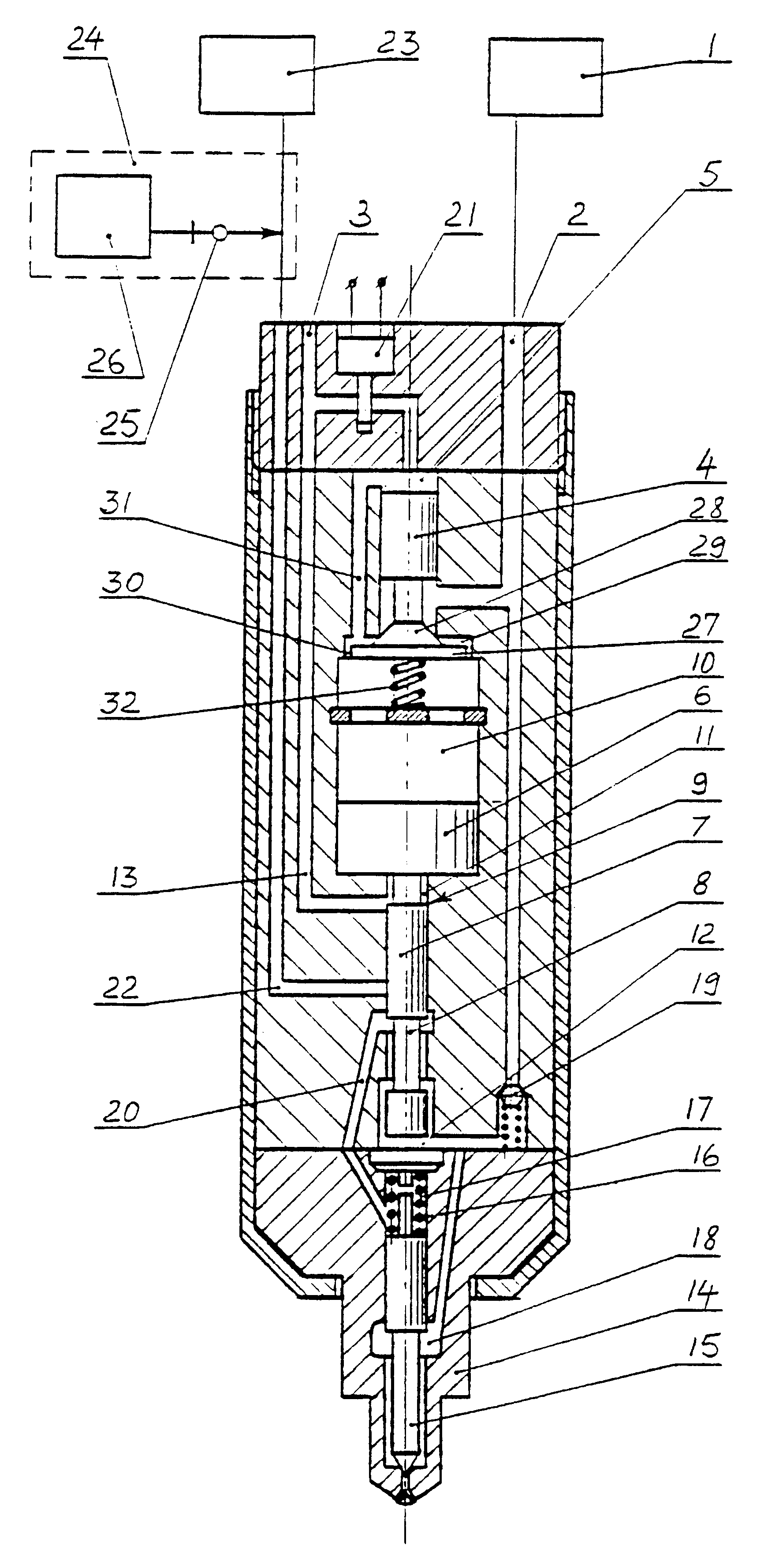
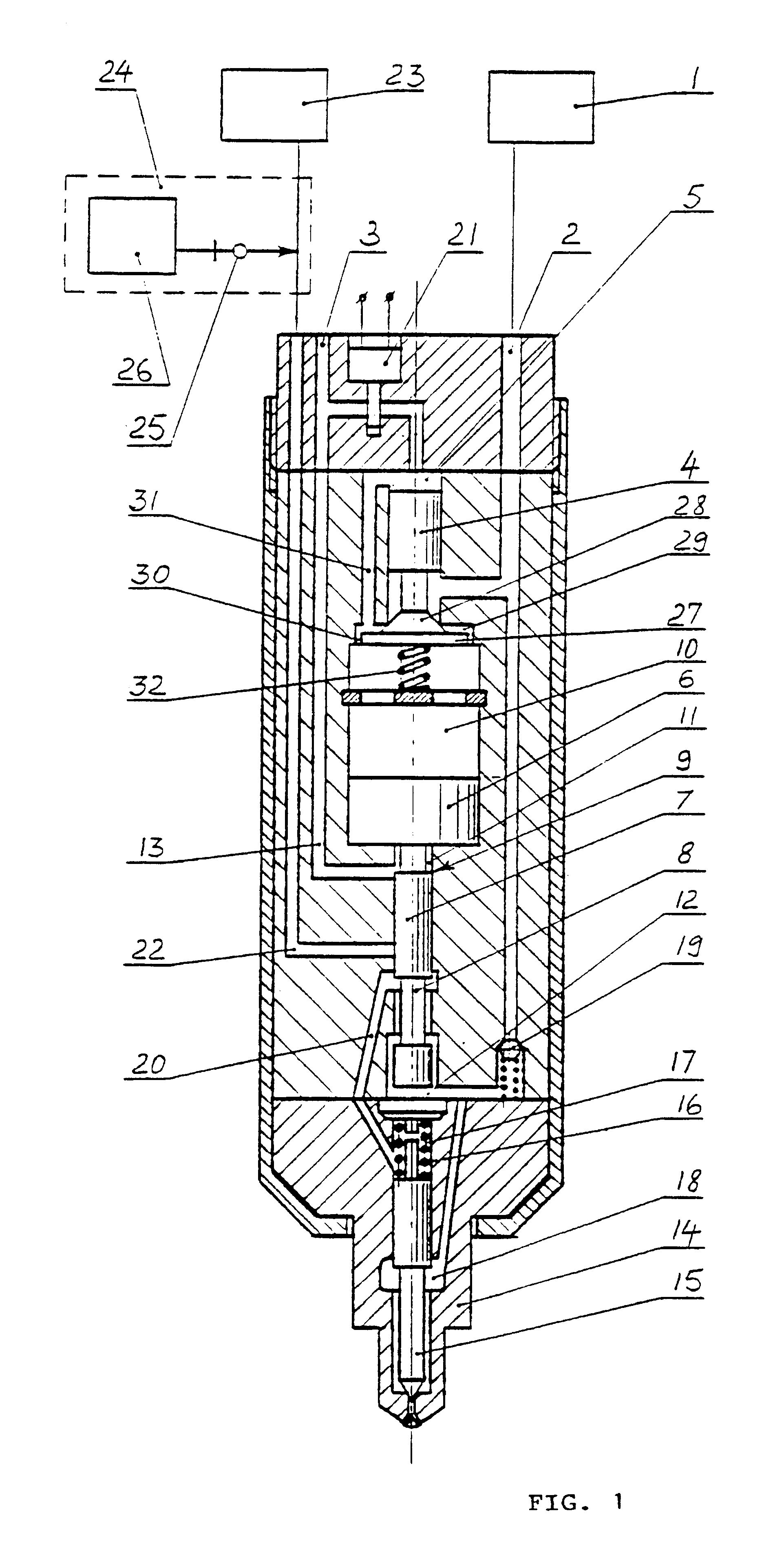
Referring to FIG. 1, in the initial position the solenoid valve 21 is inert and closes off the connection between HDV control chamber 5 and spill port 3. The HDV 4 is closed, the piston 6 and plunger 7 are kept in the bottom position by the fuel pressure in the working chamber 10, the locking chamber 17...


PUM


Abstract

A hydraulically actuated electronically controlled fuel injection system comprises a pressure intensifier (6, 7) associated with a hydraulically controlled differential valve (4) having a poppet valve (27) opening into a working chamber (10) of the pressure intensifier (6, 7). An external groove (8) is provided on the plunger (7) of the intensifier (6, 7) for connection of the plunger's compression chamber (12) with a nozzle's locking chamber (17) during an injection cut-off period.

Description

The present invention relates to a system and means for injecting fuel into internal combustion engines.Some fuel injection systems have been designed as unit injectors which incorporate an hydraulically driven pressure intensifier with a stepped plunger for injecting fuel into an engine's cylinder where the fuel delivery and timing are controlled by an electronically controlled valve. The spray pattern of each injector is controlled by means of modulating the base oil pressure supplied to each unit injector.It is known that in many diesel engines the optimum injection curve shapes vary depending on the engine's operating conditions. A pilot injection of a small amount of fuel separate from a main injection may be required at some operating conditions and a boot-shaped injection at other conditions, or a sharp leading front of an injection curve may be the best for another engine speed and load. The correlations between engine operating conditions and the optimum shapes of the injec...

Claims


Application Information

Patent Timeline
IPC IPC(8): F02M57/00F02M57/02F02M45/00F02M47/02F02M47/00
CPCF02M45/00F02M47/02F02M47/027F02M57/025
Inventor YUDANOV, SERGIMITCHELL, WILLIAM RICHARD
Owner ENVIRO DIESEL SYST PTY LTD
Why Eureka
Try Eureka