System and method for providing multicharge ignition

a multi-charge ignition and ignition system technology, applied in the direction of mechanical equipment, machines/engines, electric control, etc., can solve the problems of high cost, complex circuitry, and failure to achieve successful energy pulses to contribute to the desired combustion process, etc., to achieve the effect of even if they exist, and reducing the cost of high-temperature filter capacitors

Inactive Publication Date: 2001-04-10
DELPHI TECH IP LTD
View PDF3 Cites 35 Cited by
  • Summary
  • Abstract
  • Description
  • Claims
  • Application Information

AI Technical Summary

Benefits of technology

Yet another object of the present invention is to provide a multicharge ignition system and method adapted to terminate the sequence of recharging and partially discharging the inductive energy storage device based on a timing signal (e.g., from an existing PTCU, such as an EST signal) and without requiring other signals indicative of crank angle.
Also provided by the present invention, in an internal combustion engine having a timing control unit, a plurality of combustion chambers, and at least one spark plug in each combustion chamber, is a multicharge ignition system connected to each spark plug and also connected to the timing control unit. The multicharge ignition system comprises an inductive engery storage device for each combustion chamber and electronic ignition circuitry for each combustion chamber. Each inductive energy storage device has primary and secondary sides inductively coupled to one another. Each electronic ignition circuitry is connected to a respective primary side of a respective inductive energy storage device and is adapted to receive, from the timing control unit, a respective timing signal indicative of when firing of a respective spark plug is to commence. Each electronic ignition circuitry is responsive to its respective timing signal by charging its respective inductive energy storage device by flowing electrical current through the primary side thereof until a predetermined amount of energy is stored therein. Each electronic ignition circuitry is further adapted to discharge a portion of the predetermined amount of energy through the secondary side of its respective inductive energy storage device by opening a path of the electrical current through the primary side upon achieving the predetermined amount of energy in the respective inductive energy storage device. Each electronic ignition circuitry is further adapted to close the path and reopen the path repetitively to recharge and partially discharge, respectively, its respective inductive energy storage device. Each electronic ignition circuitry is further arranged so that reopening of the path is triggered based on the amount of energy stored in the inductive energy storage device. The ignition circuitry is further adapted to terminate the sequence of recharging and partially discharging the inductive energy storage device based on the respective timing signal and without requiring other signals indicative of crank angle.

Problems solved by technology

The multistrike approach is capable of delivering somewhat more energy at very low speeds, but with the limitation that the successive energy pulses are too late to contribute to the desired combustion process.
While AC ignition could provide performance similar to the multicharge approach, it does so at a much higher cost and using more complex circuitry.
Such high temperature filter capacitors, even if they exist, can be very expensive.

Method used


Image

  • System and method for providing multicharge ignition
  • System and method for providing multicharge ignition
  • System and method for providing multicharge ignition

Examples


Embodiment Construction

The preferred embodiments of the present invention will be described in the context of an internal combustion engine having a certain number of cylinders. It is understood, however, that the invention can be applied to engines having any number of cylinders, as well as engines having non-cylindrical combustion chambers (e.g., rotary engines).

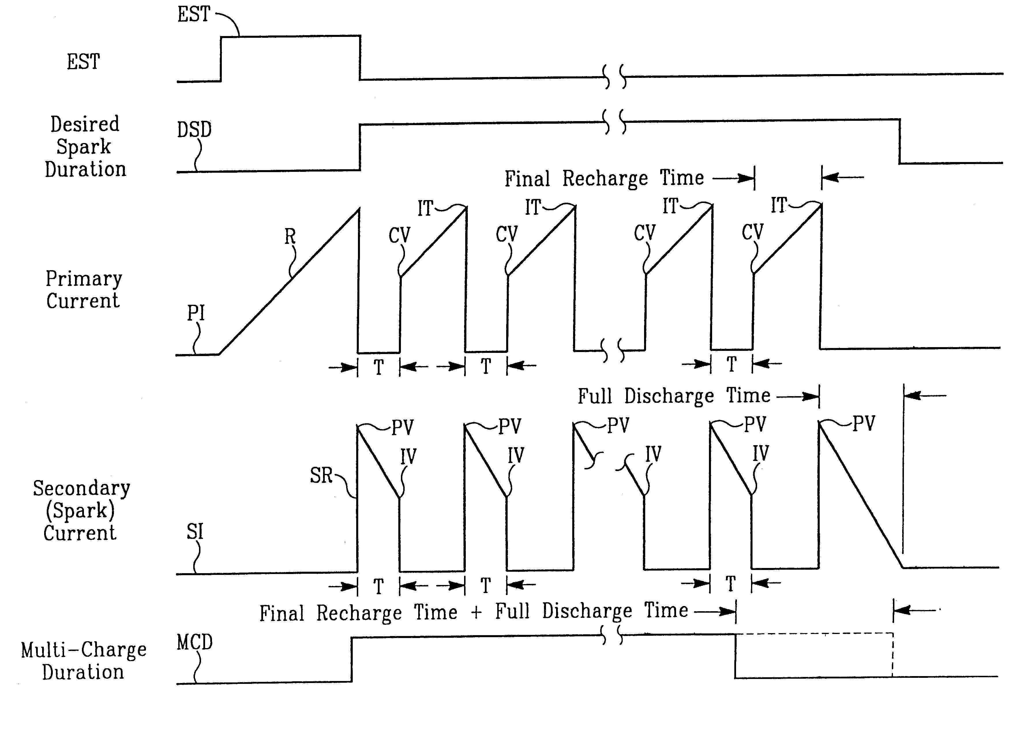
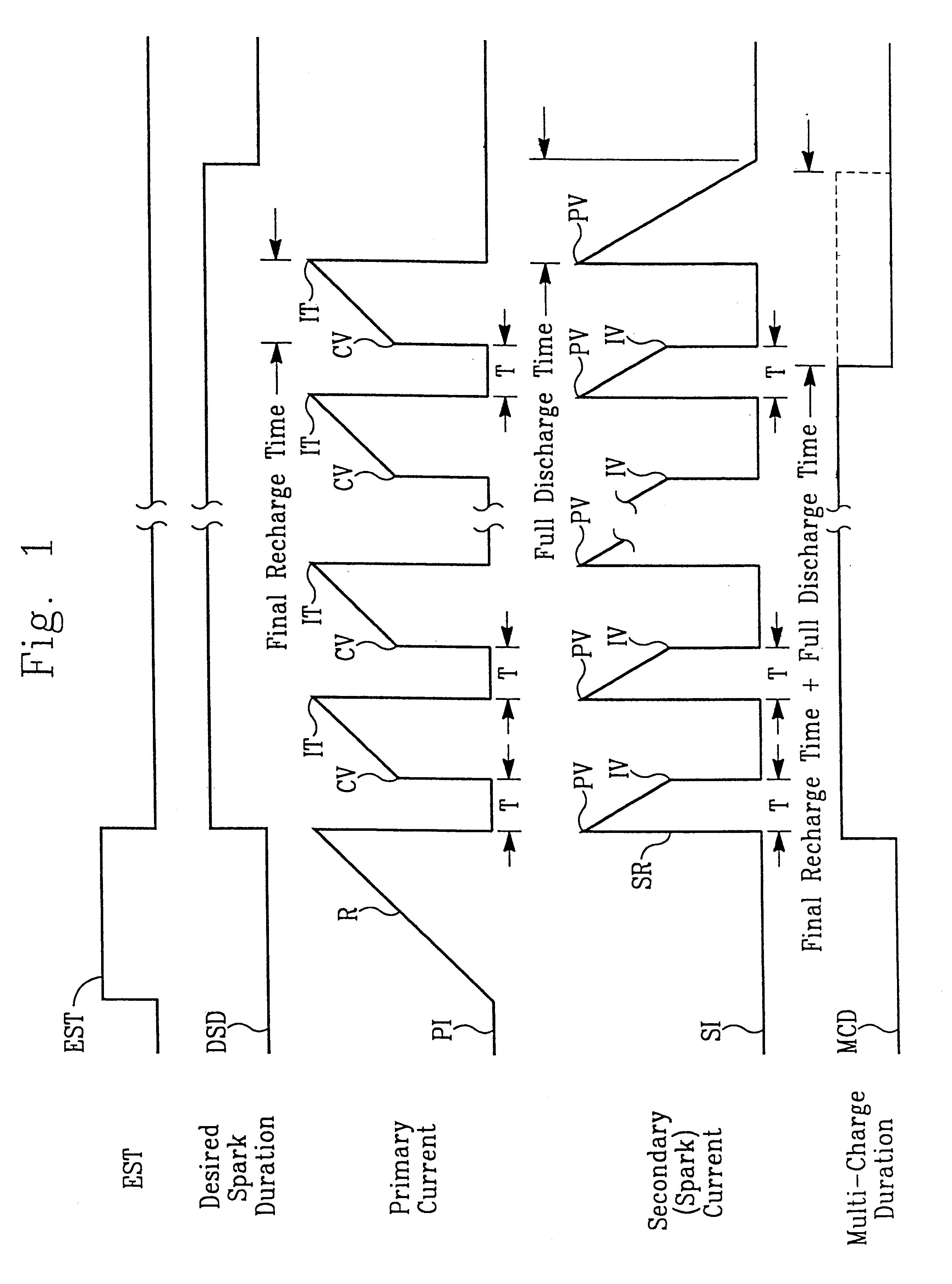
FIG. 1 is a timing diagram of a multicharge method according to a preferred implementation of the present invention. EST in FIG. 1 denotes a timing signal which is generated by the power train control unit (PTCU) of many production vehicles. The EST signal indicates when the next firing of a spark plug is to commence. Typically, one EST pulse is delivered for each firing. Thus, in an eight-cylinder, four-stroke engine, for example, each pair of revolutions of the engine will result in eight EST pulses of the type illustrated in FIG. 1. The EST pulses are temporally separated and used to trigger a sparking event in one or more of the combustion c...


PUM


Abstract

A system and method of providing multicharge ignition are provided. The method and system preferably are adapted to trigger at least some of the multicharge events of the system and method in a current-dependent manner. Preferably, existing power train control units (PTCUs) can be used with the system and method, without the need for signals other than the timing signal (e.g., EST pulse) from the PTCU. The method comprises the steps of charging an inductive energy storage device by flowing electrical current through a primary side of the inductive energy storage device until a predetermined amount of energy is stored therein, discharging a portion of the predetermined amount of energy through a secondary side of the inductive energy storage device by opening a path of the electrical current through the primary side upon achieving the predetermined amount of energy in the inductive energy storage device, and repetitively closing and reopening the path to recharge and partially discharge, respectively, the inductive energy storage device, wherein reopening of the path is triggered based on the amount of energy stored in the inductive energy storage device. The multicharge ignition system comprises an inductive energy storage device and electronic ignition circuitry. The inductive energy storage device has primary and secondary sides inductively coupled to one another. The electronic ignition circuitry is connected to the primary side and is adapted to implement the aforementioned method.

Description

The present invention relates to a system and method for providing multicharge ignition, and more specifically, to a method and system adapted to trigger at least some of the multicharge events of the system and method in a current-dependent manner and further adapted to terminate the sequence of recharging and partially discharging the inductive energy storage device of the ignition system based on a timing signal and without requiring other signals indicative of crank angle.Generally, a repetitive spark distributorless ignition system stops ignition current before the complete discharge of magnetic energy in the ignition coil supplying the spark plug. During the stoppage, the ignition coil is recharged so an additional spark can be applied to the spark plug. The present invention relates to a system and method for igniting a combustible gaseous mixture, particularly a mixture of gasoline vapor and air in the combustion chamber of an internal combustion engine utilizing a spark plu...

Claims


Application Information

Patent Timeline
Patent Type & Authority Patents(United States)
IPC IPC(8): F02P3/02F02P9/00F02P3/045
CPCF02P3/02F02P3/0453F02P9/007F02D2041/2075
Inventor BOYER, JAMES ALVABRACKEN, NORMAN H.BUTLER, JR., RAYMOND O.
Owner DELPHI TECH IP LTD
Why Eureka
Try Eureka