Pressure control device

a control device and pressure control technology, applied in printing and other directions, can solve the problems of inability to overcome the back pressure inability to print head, and inability to eject ink drops, etc., and achieve the effect of restricting the variation of back pressur

Inactive Publication Date: 2001-04-10
TRANSPACIFIC IP LTD
View PDF4 Cites 84 Cited by
  • Summary
  • Abstract
  • Description
  • Claims
  • Application Information

AI Technical Summary

Benefits of technology

Accordingly, the present invention is to provide a pressure control device capable of restricting the variatio

Problems solved by technology

However, the back pressure can not be so high that the print head is unable to overcome the back pressure to eject ink drops.
Without regulation of this back pressure increase, the ink-jet pen will fail soon because the back pressure is too high that the print head can not overcome it to eject ink drops.
However, although the accumulators such as elastomeric bags can adjust automatically the reservoir volume to keep the back pressure within the operation range, the extent to which elastomeric bags are capable of expanding is quite limited.
Consequently, when ink gradually drops from the print head, the bag may reach its maximum extent and therefore incapable of any further adjustment of the reservoir volume.
Thirdly, the bubble generator must have self-wetting capability.
In addition, static pressure of the ink column within the reservoir can affect the value of back pressure required before air bubbles begin to enter the reservoir.
1. The value of back pressure within the ink-jet reservoir before bubble generator s

Method used


Image

  • Pressure control device
  • Pressure control device
  • Pressure control device

Examples


example 1

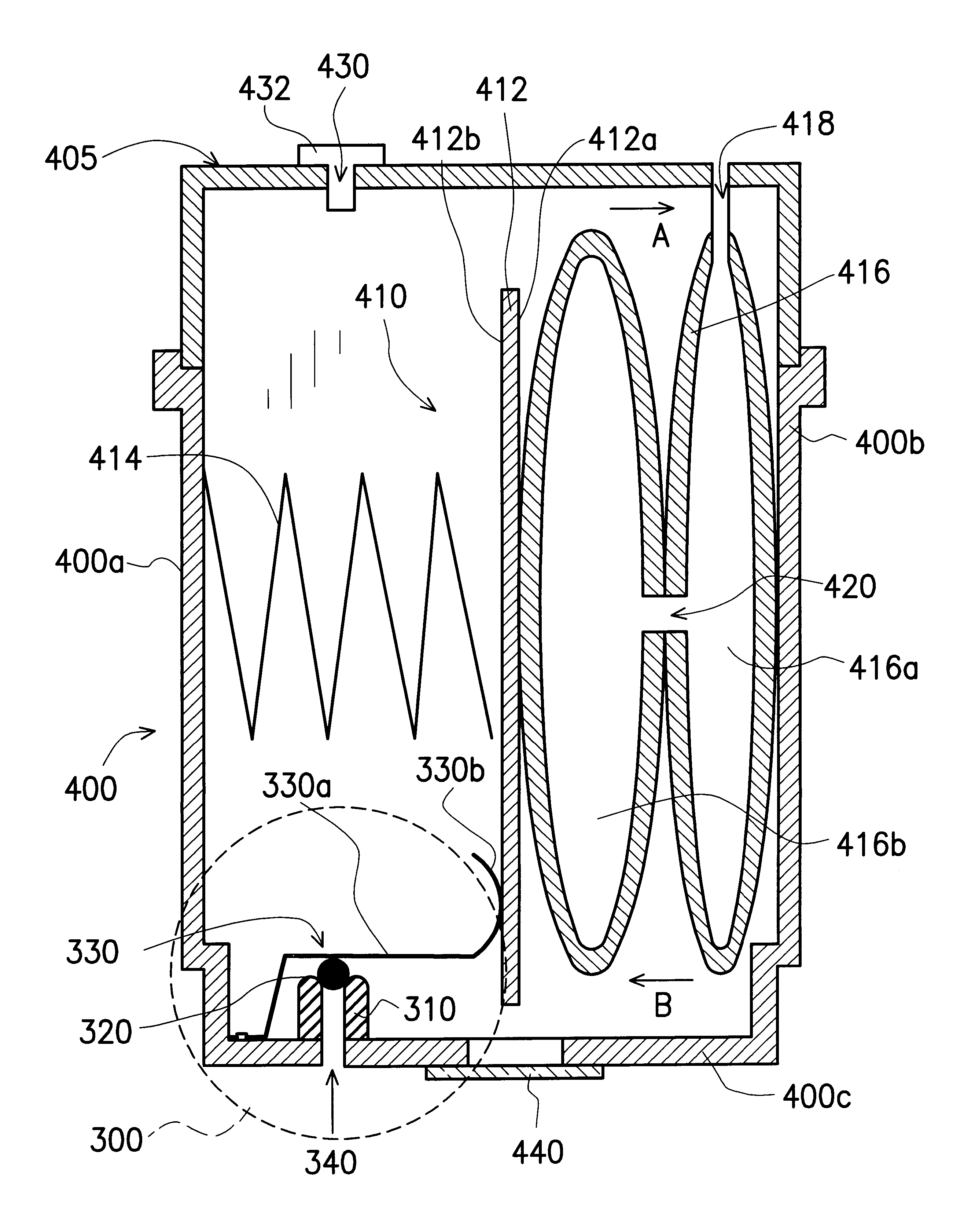
FIGS. 3A and 3B are cross-sectional views showing the components inside an ink-jet pen including an expandable bag 416 in the contracted position to the embodiment of this invention. As show in FIG. 3A, the ink-jet pen 400 is actually a reservoir having rigid sidewalls 400a, 400b, 400c and a cap 405. Inside the ink-jet pen 400, there is an accumulator 410. The accumulator 410 is in fact an assembly of components that includes a pressure plate 412, a spring 414 and an expandable bag 416. The bag 416 further includes a first chamber 416a and a second chamber 416b. The first chamber 416a is connected to ambient air via a connecting pipe 418. Consequently, ambient air is able to flow into and out of the bag 416. The connecting pipe 418 passes through the cap 405 of the ink-jet pen with its end tightly sealed. Therefore, the only path for air into and out of the bag is through the connecting pipe 418. Between the first chamber 416a and the second chamber 416b, there is an opening 420 per...

example 2

FIGS. 4A and 4B are cross-sectional views showing the components inside an ink-jet pen including a number of expandable bags (for example, two separate bags) in the expanded / contracted position to another embodiment of this invention.

As show in FIG. 4A, the ink-jet pen 500 is actually a reservoir having rigid sidewalls 500a, 500b, 500c and a cap 505. Inside the ink-jet pen 500, there is an accumulator 510. The accumulator 510 is in fact an assembly of components that includes a number of pressure plates (for example, two plates 512a, 512b), a spring 514 and two expandable bags 516a, 516b. The bags 516a, 516b are connected to ambient air via connecting pipes 518a, 518b. Consequently, ambient air is able to flow into and out of the bag 516a, 516b. The connecting pipes 518a, 518b passe through the cap 505 of the ink-jet pen 500 with its end tightly sealed. Therefore, the only path for air into and out of the bags 516a, 516b are through the connecting pipes 518a, 518b.

As shown in FIG. 4...

example 3

FIG. 5 is a cross-sectional view showing a pressure control device according to this invention. The pressure control device is installed at the bottom part 400c of an ink-jet pen 400. Position of the pressure control device includes a tubular boss 310 having an arc surface 312 at its upper end. A sphere 320 sits on top of the arc surface 312. Ideally, the sphere 320 should form a line contact with the arc surface 312 of the boss 310. A flat spring 330 is fixed by a rivet 332 to the bottom 400c of the ink-jet pen. The flat spring 330 includes a first portion 330a and a second portion 330b. The first portion 330a of the flat spring 330 will press on the sphere 320 tightly while the second portion 330b is in contact with a pressure plate 412 next to it. In addition, there is an expandable bag 416 on one side of the ink-jet pens 400. As the bag 416 expands, the pressure plate 412 will push the second portion 330b of the flat spring 330, thus lifting the first portion 330a away from the ...


PUM


Abstract

A pressure control device installed at the bottom of the reservoir of an ink-jet pen. The device has a tubular boss whose upper end has an arc surface and that a sphere sits on the arc surface. Ideally, the sphere makes a line contact with the arc surface of the boss. The device also has a spring with one end mounted to the bottom of the reservoir. The spring has two portions together. The first portion of the spring presses tightly against the sphere while the second portion touches a pressure plate inside the reservoir. The reservoir further contains an expandable bag. When the bag inside the reservoir expands, the pressure plate attached to the bag will push the second portion of the spring such that its first portion will move away from the sphere. Due to the presence of a back pressure within the reservoir, the sphere will be afloat briefly permitting ambient air to enter the reservoir. Consequently, back pressure within the reservoir is regulated.

Description

This application claims the priority benefit of Taiwan application serial no. 87116229, filed Sep. 30, 1998, the full disclosure of which is incorporated herein by reference.1. Field of InventionThe present invention relates to a pressure control device. More particularly, the present invention relates to a pressure control device for controlling the pressure within the ink reservoir of an ink-jet pen.2. Description of Related ArtConventional ink-jet printing generally relies on the controlled delivery of ink droplets from an ink-jet pen ink reservoir to a print medium. Among the printing methods for delivering ink drops from the ink reservoir to the print head, drop-on-demand printing is known as the commonly used method. Drop-on-demand method typically uses thermal bubble or piezoelectric pressure wave mechanisms. A thermal bubble type print head includes a thin film resistor that is heated to cause sudden vaporization of a small portion of ink. The vapid expansion of the ink vapo...

Claims


Application Information

Patent Timeline
IPC IPC(8): B41J2/175
CPCB41J2/17513B41J2/17556
Inventor HOU, I. C.LIN, CHI-CHIEN
Owner TRANSPACIFIC IP LTD
Why Eureka
Try Eureka