Power-on reset circuit for dual-supply system

a dual-supply system and power-on technology, applied in the field of circuitry, can solve the problems of unsatisfactory source of power consumption, reducing operating efficiency, and causing signal propagation delays

Inactive Publication Date: 2001-04-10
SEMICON COMPONENTS IND LLC
View PDF4 Cites 32 Cited by
  • Summary
  • Abstract
  • Description
  • Claims
  • Application Information

AI Technical Summary

Problems solved by technology

Furthermore, minor potential swings in TTL signals, and low voltage TTL (LVTTL) swings in particular, may not effect any logic level change associated with CMOS transistors connected thereto.
This current is known as simultaneous conduction current or leakage current and is an undesirable source of power consumption.
Unfortunately, there exists a problem with the use of the translator sub-circuit 40 shown in FIG. 2 in combination with the reset circuit 10 shown in FIG. 1.
This results in the undesirable development of the leakage current that draws power unnecessarily from the system and reduces operating efficiency.
More generally, it is to be noted that translation circuits use power, create signal propagation delays, may not provide full translation, and inherently take up premium circuit space.
Third, even with the second supply off, the logic signal input associated with the first power supply is irrelevant to the reset operation due to the control of the reset signal by the logic gate.

Method used


Image

  • Power-on reset circuit for dual-supply system
  • Power-on reset circuit for dual-supply system
  • Power-on reset circuit for dual-supply system

Examples


Embodiment Construction

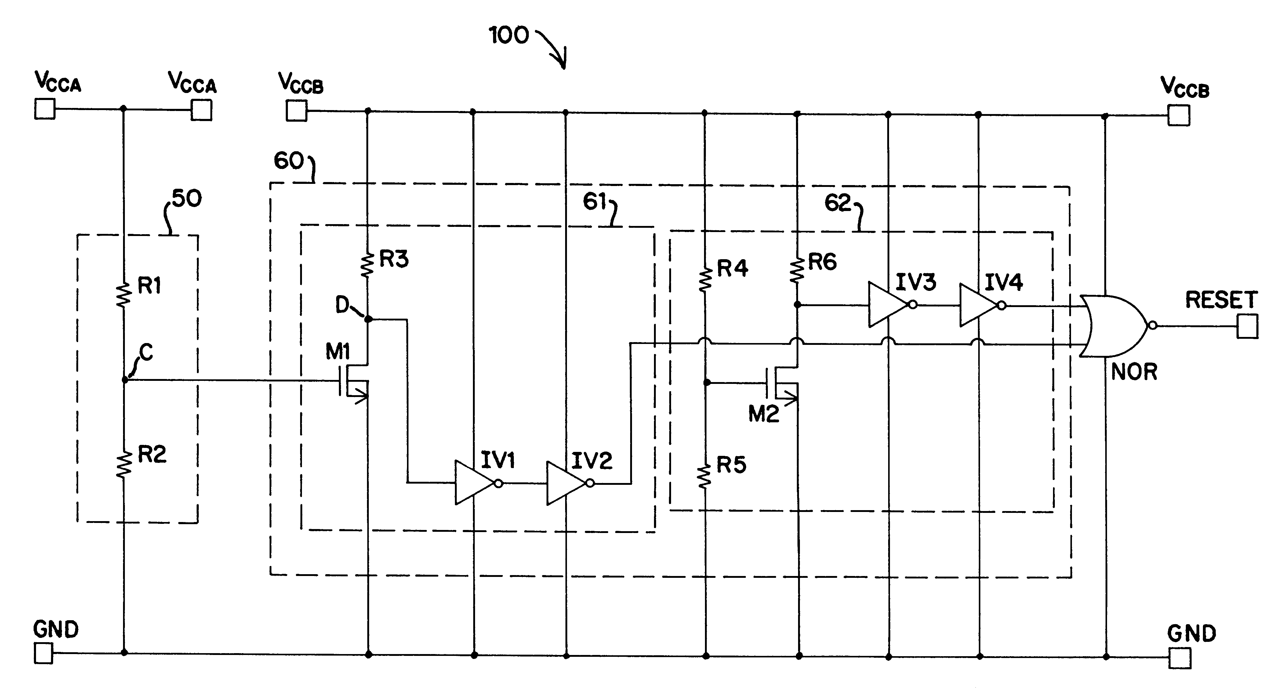
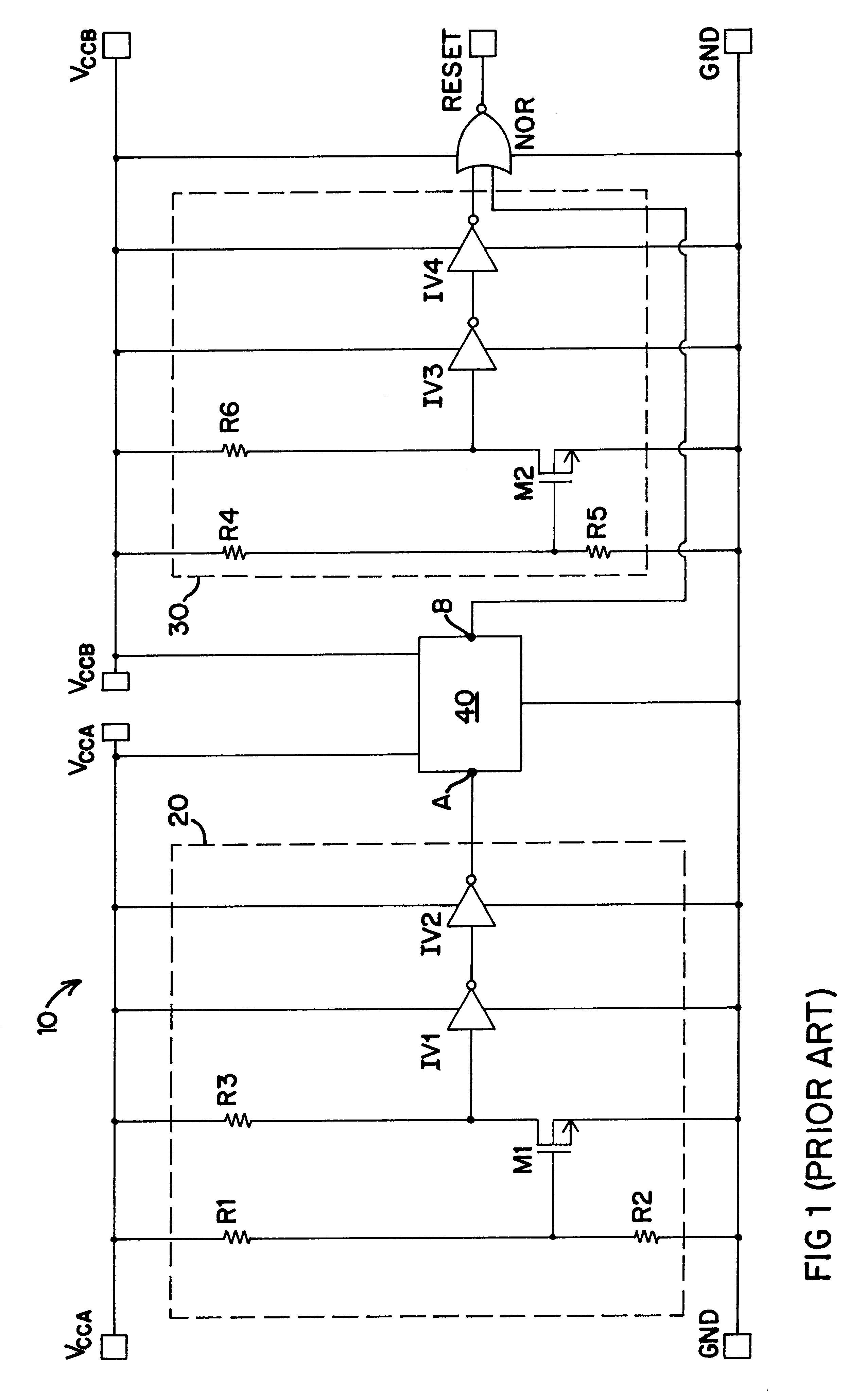
A simplified illustration of a power-on reset circuit 100 of the present invention is shown in FIG. 3. Those components included in the circuit 100 of the present invention that are the same as the components of the prior-art circuit 10 shown in FIG. 1 are designated by like numbers. The reset circuit 100 includes a reset regulating branch 50 powered by first high-potential power rail Vcca of some specified potential. The reset circuit 100 further includes a translation and reset sub-circuit 60 powered by second high-potential power rail Vccb of some specified potential different than that of the potential of rail Vcca. An output of branch 50 is coupled to an input of circuit 60 at node C. Specifically, node C supplies a signal to first-supply-regulated sense circuit 61 so as to regulate an input signal to a logic gate such as NOR gate NOR, or any other suitable logic device capable of evaluating the input signals to produce a selected output signal. A second circuit, second-supply-...


PUM


Abstract

A power-on reset circuit for a dual-supply system. The reset circuit includes a voltage divider powered by the first power supply and a sub-circuit supplied by the second power supply. The output of the voltage divider is connected to a control node of the first reset sub-circuit that is otherwise powered by the second power supply. A second reset sub-circuit is strictly regulated and powered by the second power supply. The first reset sub-circuit provides for translation of a signal having a potential limited by the potential of the first supply into a signal having a potential associated with that of the second supply. Only when a control signal from the voltage divider reaches a certain potential, and the second power supply reaches a certain potential, is the first reset sub-circuit activated in a manner that results in a circuit output signaling both supplies are at a suitable potential. This is useful for hot insertion applications in dual-supply systems.

Description

1. Field of the InventionThe present invention relates to circuitry for generating power-on reset signals for transmission to integrated circuit systems. In particular, the present invention relates to a power-on reset circuit that operates to hold off power-on reset until the high-potential power supply rail reaches a defined potential. More particularly, the present invention relates to power-on reset circuitry that operates as required when coupled to circuitry powered by supplies of differing potentials. The present invention is a power-on reset circuit used in association with logic level translation systems.2. Description of the Prior ArtPower-on reset circuits are designed to transmit to semiconductor-based systems signals to enable operation of such systems only when a common high-potential power rail reaches a certain minimum potential. These power-on reset circuits may be used to enable "hot" or live insertion of systems or subsystems such as circuit boards that are initia...

Claims


Application Information

Patent Timeline
Patent Type & Authority Patents(United States)
IPC IPC(8): G06F1/24H03K17/22
CPCG06F1/24H03K17/223
Inventor MORRILL, DAVID P.
Owner SEMICON COMPONENTS IND LLC
Why Eureka
Try Eureka